


M
Mary RodriguezAug 21, 2025
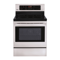
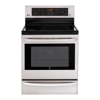
Why are the clock and timer not working on my LG LRE3061ST Ranges?
- MMichael LeeAug 21, 2025
If the clock and timer aren't working on your LG Ranges, first verify that power is present at the unit and ensure that the circuit breaker is not tripped. Replace the household fuse, if necessary, ensuring you do not exceed the original fuse capacity. A power outage could also be the reason.