PRODUCT DATA | 27
Product Data
Due to our policy of continuous product innovation, some specications may change without notication.
© LG Electronics U.S.A., Inc., Englewood Cliffs, NJ. All rights reserved. “LG ” is a registered trademark of LG Corp.
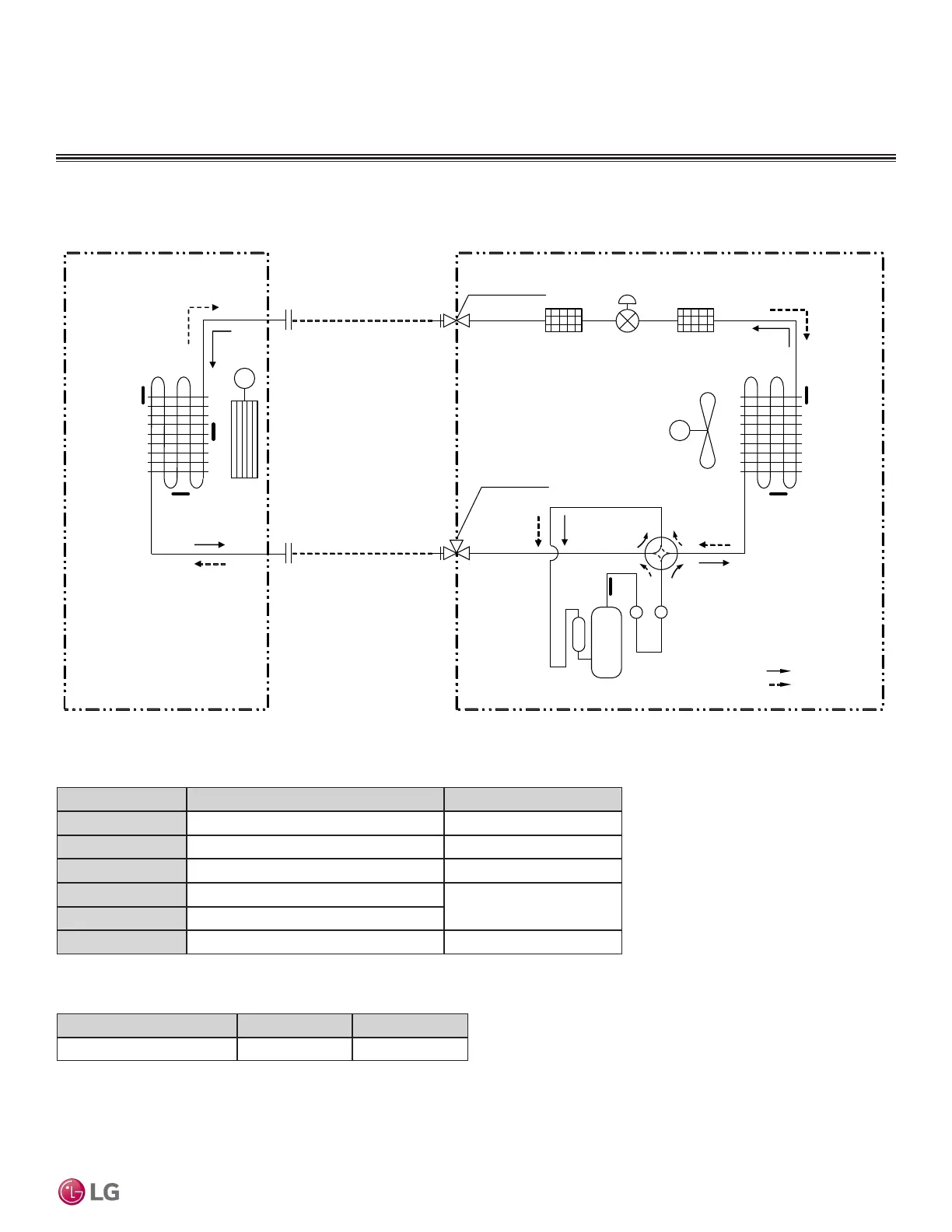
REFRIGERANT FLOW DIAGRAMS
Mega 115V Models
Refrigerant Flow Diagram for LS090 ~ 120HXV2 models
Table 13: Mega 115V LS090 ~ 120HXV2 Thermistor Details.
Table 14: Mega 115V LS090 ~ 120HXV2 Refrigerant Piping Sizes.
Model No. Vapor (Inch [mm]) Liquid (Inch [mm])
LS090HXV2, LS120HXV2 Ø3/8 (Ø9.52) Ø1/4 (Ø6.35)
Mufflers
Strainer
Field Pipin g
(Copper Tubing)
Field Piping
(Copper Tubing)
M
M
Heat
Exchanger
(Evaporator)
Heat
Exchanger
(Condenser)
Compressor
2-Way Valve
Reversing
Valve
(4-Way
Valve)
Indoor Unit Outdoor Unit
: Cooling
: Heating
EEV
TH1
TH2
TH4
TH5
TH6
Liquid Side
Vapor Side
3-Way Valve
TH3
Propeller
Fan
Cross
Flow
Fan
Flare
Joint
Flare
Joint
(Electronic
Expansion
Valve)
Strainer
Thermistor Description PCB Connector
TH1
Indoor air temperature thermistor CN-TH1 (Indoor)
TH2
Evaporator temperature thermistor CN-TH3 (Indoor)
TH3
Water Level Sensor (Option) CN-TH2 (Indoor)
TH4
Outdoor air temperature thermistor
CN-TH1 (Outdoor)
TH5
Condenser temperature thermistor
TH6
Discharge pipe temperature thermistor CN-TH2 (Outdoor)
 Loading...