- 21 -
1. EXPLANATION FOR PCB CIRCUIT
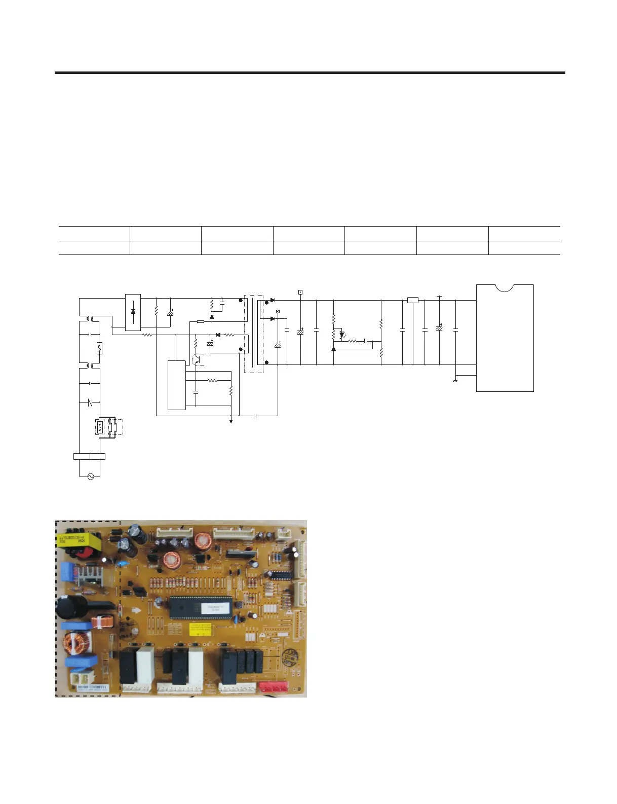
1-1. Power circuit
The power circuit includes a Switched Mode Power Supply (SMPS). It consists of a rectifier (BD1 and CE1) converting AC
to DC, a switch (IC2) switching the DC voltage, a transformer, and a feedback circuit (IC3 and IC4).
Caution : Since high voltage (160 Vdc) is maintained at the power terminal, wait at least 3 minutes after unplugging the
appliance to check the voltages to allow the current to dissipate.
Voltage of every part is as follows:
6.EXPLANATION FOR MICOM CIRCUIT
Part VA1 CE1 CE2 CE3 CE4 CE5
160 Vdc 14 Vdc 12 Vdc 15.5 Vdc 5 Vdc
The part highlighted in green, are the
components of the Switched Mode
Power Supply
275V
AC
1.3A,40mH
L2
1
FUSE2
1/2W
CM2
BD1
CE1
R1(PRC)
D3SBA60
R2(PRC)
220nF
4
4
330K, 1W
560K
/400V
68uF
250V/5A
1
CM3
473
D3
TRANS
RL3
10
FR107
FB1
D1
/630V
RL3
12
D4
2
+16V
R8*
CC30* CC31*
1/8W
1.8K
+12V
CE2
FR107
22uF
5
68,1/8W
CE4
1000uF
4
/35V
/50V
KIA431
1K
10K,1/8W
IC3
2
R9*
1
1000uF
IC4
/25V
R89*
CE3
1/8W
D2
104104
R5*
FUSE1
POWER
IC2
275VAC
3
250V/15A
1
CON1
5
G6351
VA1
L1
SVC621-200V
STR
7A,2mH
TAB2(L)
(SVC331-100V)
CM1
2
2
TAB1(N)
330nF
JF1JF2
Rocp
0.68,1W
680
471
CC2
CC1*
221/400V
R6
56K,2W
8
1/8W
3
R3(PRC)
R4*
6.8K
2
/16V
32
104
1/8W
CC4*
1/8W
RF2*
104
Vss
104
54
26
IC5
RF3*
IC1
MICOM
9.1KF
104
1
Vass
2.4KF
CC6*
220uF
CC3*
CC5*
55
CE5
5V
TEST
64
7805
VDD
3
Varef
Voltage 110~127 Vac
 Loading...