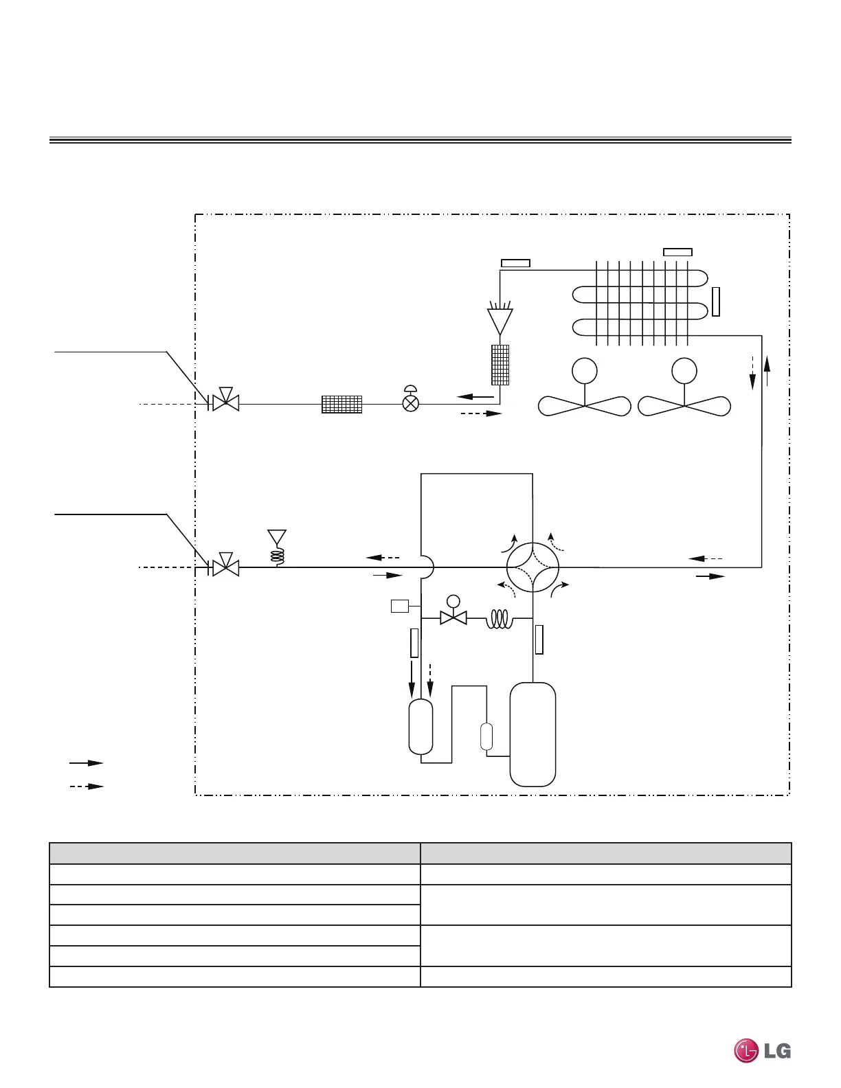
Refrigerant Flow Diagram
MULTI F MAX OUTDOOR UNIT
Figure 23: LMU540HV Refrigerant Flow Diagram.
M M
Discharge Pipe
Temperature
Thermistor
Suction Pipe
Temperature
Thermistor
Inverter
Accumulator
Fusible Plug
Compressor
Heat Exchanger Outlet
Temperature
Thermistor
Inlet Air
Temperature
Thermistor
Ø 3/8 Flare Connection
Heat
Exchanger Inlet
Temperature
Thermistor
: Cooling
: Heating
Pressure
Sensor
Electronic
Expansion
Valve
Ø 3/4 Flare Connection
S
Hot Gas
Bypass
Valve
Description PCB Connector
Heat Exchanger Inlet Temperature Thermistor CN-TH3
Heat Exchanger Outlet Temperature Thermistor
CN-TH1
Inlet Air Temperature Thermistor
Discharge Pipe Temperature Thermistor
CN-TH2
Suction Pipe Temperature Thermistor
Pressure Sensor CN-P/SENSOR(H)
Table 315: LMU540HV Thermistor Details.
Due to our policy of continuous product innovation, some specications may change without notication.
©LG Electronics U.S.A., Inc., Englewood Cliffs, NJ. All rights reserved. “LG” is a registered trademark of LG Corp.
328 | MULTI F MAX OUTDOOR UNIT
Multi F and Multi F MAX Heat Pump System Engineering Manual

 Loading...