31
ENGLISH
The amount of Refrigerant
The calculation of the additional charge should take into account the
length of pipe and CF(correction Factor) value of indoor unit.
Include only for
Heat Recovery
system
Total liquid pipe : Ø 25.4 mm (1.0 inch)
Additional charge(kg)
Total liquid pipe : Ø 22.2 mm (7/8 inch)
Total liquid pipe : Ø 19.05 mm (3/4 inch)
Total liquid pipe : Ø 15.88 mm (5/8 inch)
Total liquid pipe : Ø 12.7 mm (1/2 inch)
Total liquid pipe : Ø 9.52 mm (3/8 inch)
Total liquid pipe : Ø 6.35 mm (1/4 inch)
Number of installed HR units
CF value of indoor unit
=
+
+
+
+
+
+
+
× 0.480 kg/m (0.323 lbs/ft)
× 0.354 kg/m (0.238 lbs/ft)
× 0.266 kg/m (0.179 lbs/ft)
× 0.173 kg/m (0.116 lbs/ft)
× 0.118 kg/m (0.079 lbs/ft)
× 0.061 kg/m (0.041 lbs/ft)
× 0.022 kg/m (0.015 lbs/ft)
× 0.5 kg/EA (1.1 lbs/EA)
Amount refrigerant of Indoor units
Example) 4Way Ceiling Cassette 14.5 kW -1ea, Ceiling concealed
Duct 7.3 kW-2ea,
Wall Mounted 2.3 kW-4ea
CF = [0.64 kg (1.411 lbs)×1EA] + [0.26 kg (0.573
lbs)×2EA] + [0.26 kg (0.529 lbs)×4EA]
= 2.12 kg (4.67 lbs)
WARNING
• Regulation for refrigerant leakage
: the amount of refrigerant leakage should satisfy the following
equation for human safety.
If the above equation can not be satisfied, then follow the
following steps.
• Selection of air conditioning system: select one of the next
- Installation of effective opening part
- Reconfirmation of Outdoor Unit capacity and piping length
- Reduction of the amount of refrigerant
- Installation of 2 or more security device (alarm for gas leakage)
• Change Indoor Unit type
:
installation position should be over 2 m (6.6 ft) from the floor (Wall
mounted type ’ Cassette type)
• Adoption of ventilation system
: choose ordinary ventilation system or building ventilation
system
• Limitation in piping work
: Prepare for earthquake and thermal stress
!
Volume of the room at which Indoor Unit of
the least capacity is installed
Total amount of refrigerant in the system
≤0.44 kg/m
3
(0.028 lbs/ft
3
)
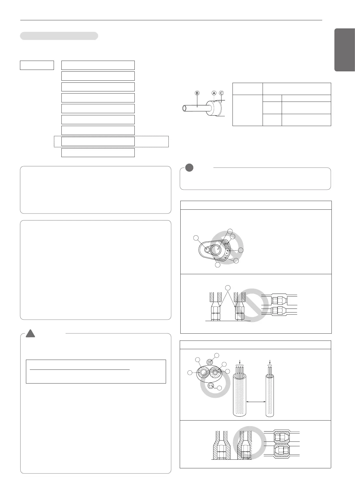
Attach the additional refrigerant table of IDU.
Bad example
• Do not insulate gas or low pressure pipe and liquid or
highpressure pipe together.
• Be sure to fully insulate connecting portion.
Ⓐ
These parts are not insulated.
Ⓐ Liquid pipe
Ⓑ Gas pipe
ⓒ Power lines
ⓓ
Finishing tape
ⓔ
Insulating material
ⓕ
Communication lines
Be sure to give insulation work to refrigerant piping by covering liquid
pipe and gas pipe separately with enough thickness heat-resistant
polyethylene, so that no gap is observed in the joint between indoor
unit and insulating material, and insulating materials themselves. When
insulation work is insufficient, there is a possibility of condensation
drip, etc. Pay special attention to insulation work to ceiling plenum.
Ⓐ Heat insulation material
Ⓑ Pipe
Ⓒ Outer covering(Wind the connection part and cutting part of heat
insulation material with a finishing tape.)
Heat insulation
material
Adhesive + Heat - resistant
polyethylene foam + Adhesive tape
Outer
covering
Indoor Vinyl tape
Floor
exposed
Water-proof hemp cloth +
Bronze asphalt
Outdoor
Water-proof hemp cloth +
Zinc plate + Oily paint
NOTE
!
When using polyethylene cover as covering material, asphalt
roofing shall not be required.
Thermal insulation of refrigerant piping
Good example
Ⓐ Liquid pipe
Ⓑ Gas pipe
ⓒ Power lines
ⓓ
Insulating material
ⓔ
Communication lines
 Loading...