44
ENGLISH
Optional Mode Selection Function Selection Option Selection
Remarks
Content
Display (◎)
Content
Display
(◀, ▶ ’ ◎)
Default
Optional
(◀, ▶ ’ ◎)
FDD Fdd
Automatic Refrigerant
Charging (Cooling)
Fd 1 - -
* Refer FDD
guidance
Automatic Refrigerant
Charging (Heating)
Fd 2 - -
Refrigerant Amount
Check (Cooling)
Fd 3 - -
Refrigerant Amount
Check (Heating)
Fd 4 - -
ITR
(Cooling, Heating)
Fd 7 - -
All IDU operation
(Cooling)
Fd 8 - -
Compulsory
Operation for
1 hour
All IDU operation
(Heating)
Fd 9 - -
Installation Func
Cool & Heat
Selector
Fn 1 oFF
oFF,
oP1~oP2
Saving in
EEPROM
High Static Pressure
Compensation
mode
Fn 2 oFF
oFF,
oP1~oP3
Night Low Noise
mode
Fn 3 oFF
oFF,
oP1~oP12
Overall Defrost
mode
Fn 4
North
America: oFF
Europe: oFF
Tropical: oN
on, oFF
ODU address
setting
Fn 5 0 254
Snow Removal &
Rapid Defrost
Fn 6 oFF
oFF,
oP1~oP3
Airflow Adjusting
for IDU (Heating
capacity up)
Fn 7 oFF on, oFF
Target Pressure
Adjusting
Fn 8 oFF
oFF,
oP1~oP6
Low Ambient Kit Fn 9 oFF on, oFF
High Efficiency
Mode (Cooling
Operation)
Fn 10 oFF on, oFF
Auto Dust Removal
Mode
Fn 11 oFF
oFF,
oP1~oP5
Compressor Max.
Frequency Limit
Fn 12 oFF
oFF,
oP1~oP9
ODU Fan Max.
RPM Limit Mode
settting
Fn 13 oFF
oFF,
oP1~oP7
Smart Load Control
Mode setting
Fn 14 oFF
oFF,
oP1~oP3
Humidity Reference
Mode setting
Fn 16 on on, oFF
Central Control
Connection at
Indoor Unit side
Fn 19 oFF oFF, on
Compressor Input
Current Limit mode
Fn 20 oFF
oFF,
oP1~oP10
Power
Consumption
Display on wired
remote controller
Fn 21 SPL0
SPL0, SPL1
[Pd10~Pd11]
Overall Defrost
Operating in Low
temperature
(Heating)
Fn 22 oFF on, oFF
Optional Base panel
Heater
Fn 23 oFF on, oFF
User Idu
Comfort Cooling
Mode setting
Id 10 EAch
* Refer
Comfort
Cooling
guidance
Saving in
EEPROM
Service SvC Vaccum Mode SE 3 vACC -
1time / 1
Selection
* Functions save in EEPROM will be maintained continuously, though
the system power was reset.
CAUTION
• To perform the otional funtion should be sure that All the IDU is off
mode, unless the function will not be performed.
!
Function setting
Master unit PCB DIP switch on : No.5
Select the mode using ‘▶’, ‘◀’ Button :
“Func” Push the ‘●’ button
Select the Function using ‘▶’, ‘◀’ Button :
“Fn1” Push the ‘●’ button
Select the Option using ‘▶’, ‘◀’ Button :
“oFF”,“op1”,“op2” Push the ‘●’ button
Cool & Heat Selection mode is set
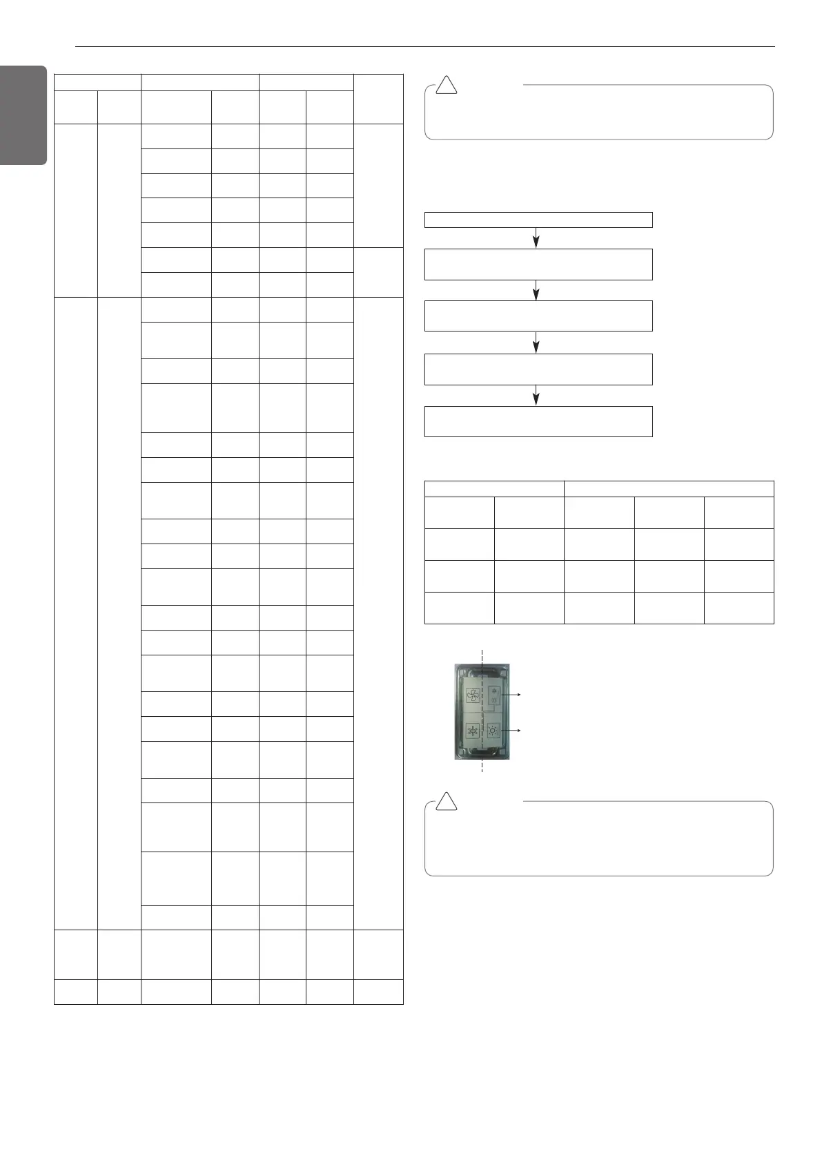
Cool & Heat selector
Mode setting method
CAUTION
• Ask an authorized technician to setting a function.
• If do not use a function, set an off-mode.
• If use a function, first install a Cool & Heat selector.
!
Switch Control Function
Switch
(Up)
Switch
(Down)
oFF op1(mode) op2(mode)
Right side
(On)
Left side
(On)
Not operate Cooling Cooling
Right side
(On)
Right side
(On)
Not operate Heating Heating
Left side
(Off)
- Not operate Fan mode Off
 Loading...