2020/07/23 page 13
5.4 CONTROL / COMMUNICATION MODBUS
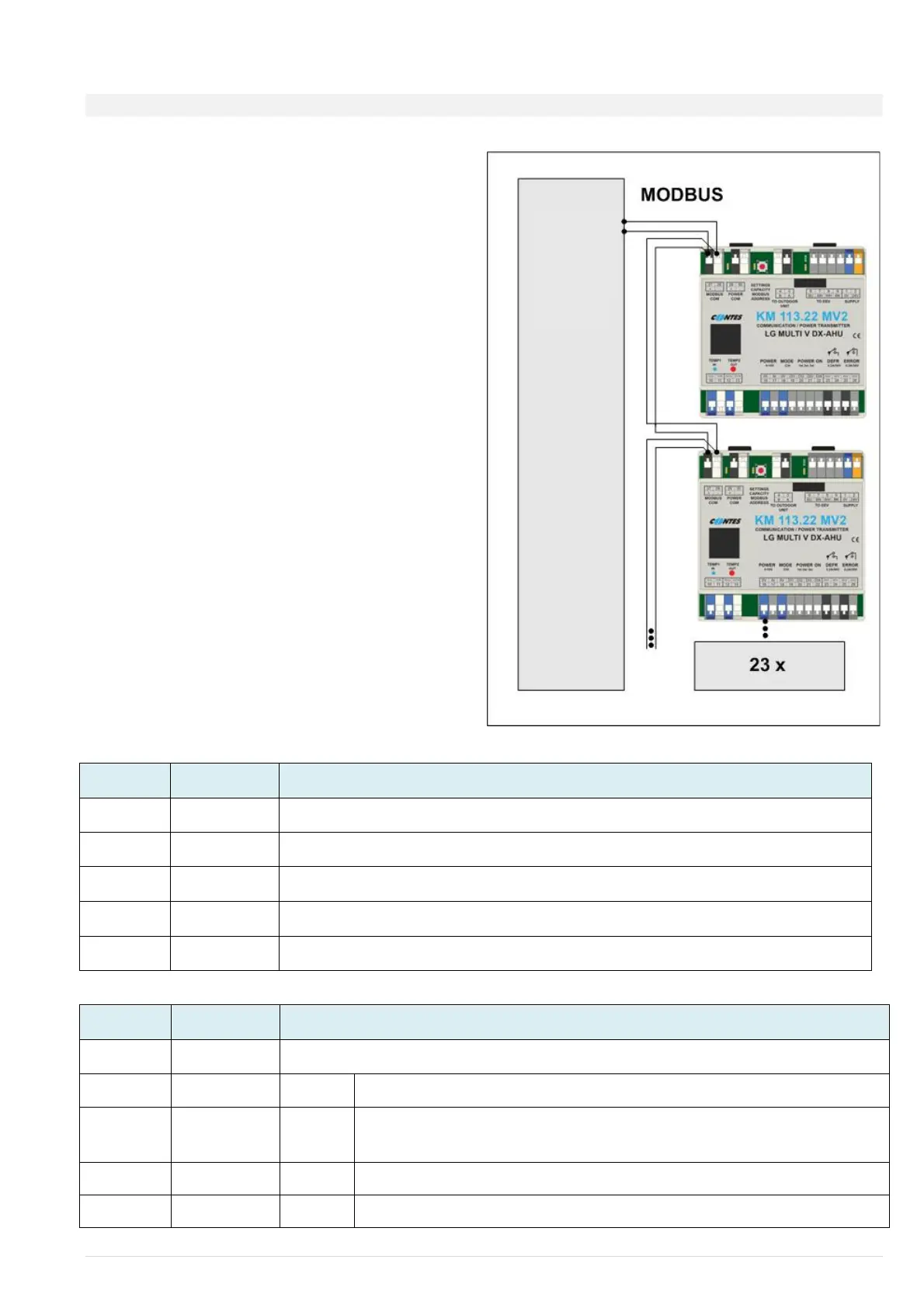
In order to control up to 23 modules from the
superior system you may use the MODBUS
communication as an option to control or monitor the
equipment.
Input/output “MODBUS“ (terminals 23+24)
The address for MODBUS communication is set using
the “SETTINGS” button. The setting procedure to be
found in paragraph 6.
PARAMETRY KOMUNIKACE MODBUS
Serial line: 9.6 kbps, 8 bits, no parity, 1 stop bit
Station address: hex91 - hexA7 (default hex91)
Supported functions: - 3 (Multi_Read)
- 6 (Single_Write)
- 16 (Multi_Write)
Fig.6 - MODBUS communication wiring diagram
for controlling multiple modules
READING REGISTRIES
Errors according to the device’s self-diagnostics (see the service manual of the
LG device), (error 99 + Modbus communication error)
Power value 0,1,2,3 (this value is used to control the power only if the
value in the registry POWER is = 0)
 Loading...