2020/07/23 page 11
“POWER LEVEL REQUEST”
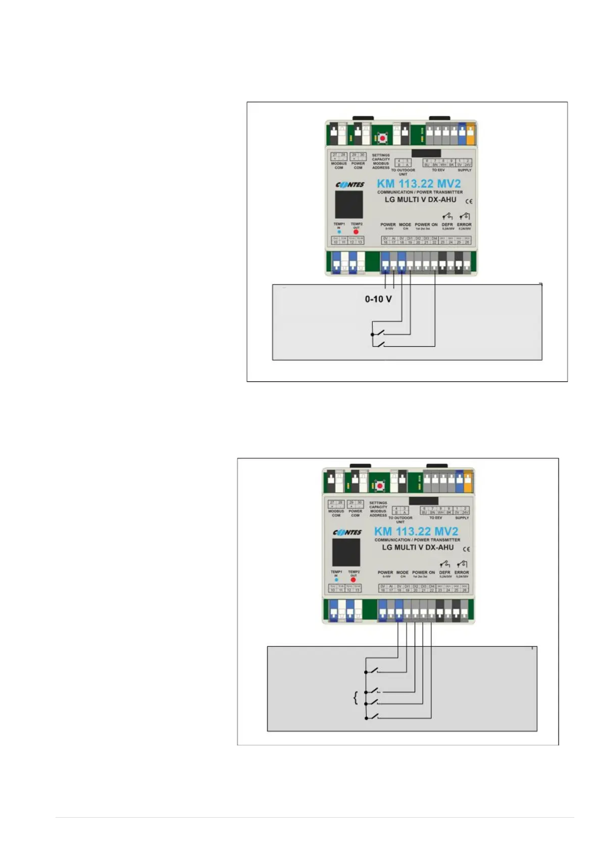
Fig.4 - Control diagram – Power request for analogue input (Operational mode through logic input)
A request for power level may be
executed through an analogue signal
0…10VDC or through 3 logic inputs
(voltage free contacts).
To directly influence the output
(change of evaporating temperature in
cooling mode/change of condensing
temperature in heat pump mode) it is
necessary to install a capacity
limitation module at the same time.
1. Input terminals “POWER 0…10V“
(terminals 16+17) – analogue
signal 0…10V (0 V = no request
for power level, 10 V = maximum
power level request). The current
power request is shown on the
right side of the display module
using 8 codes (“C0…C7“ or rather
“H0…H7“).
The power request algorithm requires
at least "C1"/"H1" code (i.e. at least
1.5V) to activate the compressor unit.
The power request algorithm requires at least "C0"/"H0" code (that means maximum 1.3V) to stop the
compressor unit.
Fig.5 - Logic input control diagram – free contact type
2. Input terminals “POWER
1ST,2ST,3ST“ – logic inputs
(voltage free contacts):
no contact closed = no
power request
contact POWER 1st closed
(terminals 18+20) = low
power request
contact POWER 2st closed
(terminals 18+21) = higher
power request
both contacts POWER
1ST+2ST closed (terminals
18+20+21) = maximum
power request
the current power demand is
displayed on the right position
of the module display via 4
codes (“C0, C1, C3, C7, “ or
“H0, H1, H3, H7”)
 Loading...