23
ENGLISH
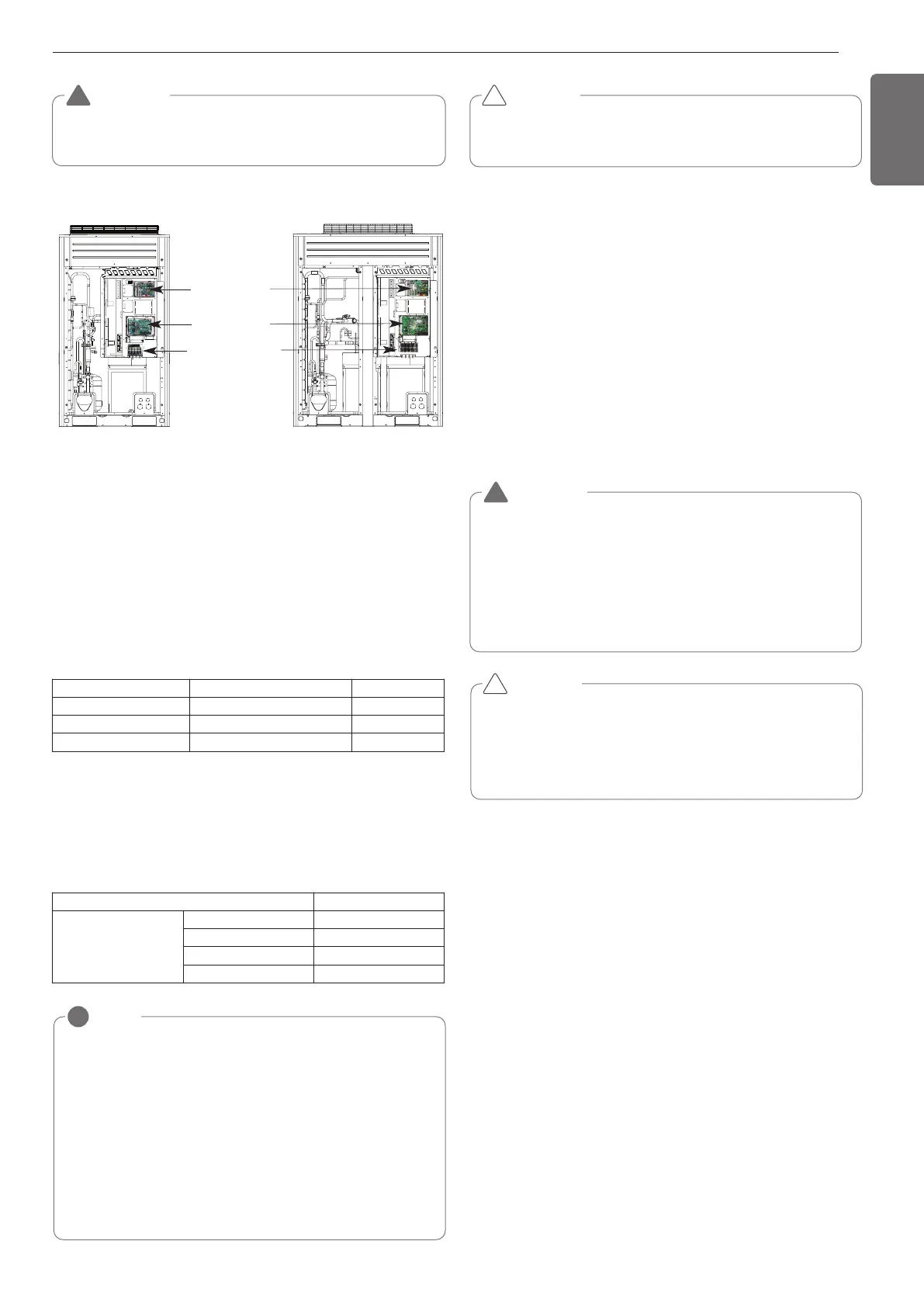
[Heat pump]
W
ARNING
The temperature sensor for outdoor air should not be exposed to
direct sunlight.
- Provide an appropriate cover to intercept direct sunlight.
!
NOTE
!
• The figures are based on assumed length of parallel cabling up
to 100 m. For length in excess of 100 m the figures will have to
be recalculated in direct proportion to the additional length of
cable involved.
• If the power supply waveform continues to exhibit some distor-
tion the recommended spacing in the table should be increased.
- If the cable are laid inside conduits then the following point
must also be taken into account when grouping various cable
together for introduction into the conduits
- Power cable(including power supply to air conditioner) and
communication cables must not be laid inside the same
- In the same way, when grouping the power wires and com-
munication cables should not be bunched together.
Product type Cable type Diameter
ACP
2-core cable (Shielding cable)
1.0~1.5mm
2
AC Smart
2-core cable (Shielding cable)
1.0~1.5mm
2
AC Ez
4-core cable (Shielding cable)
1.0~1.5mm
2
Current capacity of power cable Spacing
100V or more
10A 300mm
50A 500mm
100A 1000mm
Exceed 100A 1500mm
C
AUTION
If apparatus is not properly earthed then there is always a risk of
electric shocks, the earthing of the apparatus must be carried out by
a qualified person.
!
- Use a separate power supply for the Outdoor Unit and Indoor Unit.
- Bear in mind ambient conditions (ambient temperature,direct sun-
light, rain water,etc.) when proceeding with the wiring and connec-
tions.
- The cable size is the minimum value for metal conduit wiring. The
power cord size should be 1 rank thicker taking into account the line
voltage drops. Make sure the power-supply voltage does not drop
more than 10%.
- Specific wiring requirements should adhere to the wiring regulations
of the region.
- Power supply cords of parts of appliances for outdoor use should not
be lighter than polychloroprene sheathed flexible cord.
- Don't install an individual switch or electrical outlet to disconnect
each of indoor unit separately from the power supply.
CAUTION
• Some installation site may require attachment of an earth leakage
breaker. If no earth leakage breaker is installed, it may cause an
electric shock.
• Do not use anything other than breaker and fuse with correct ca-
pacity. Using fuse and wire or copper wire with too large capacity
may cause a malfunction of unit or fire.
!
WARNING
• Follow ordinance of your governmental organization for techni-
cal standard related to electrical equipment, wiring regulations
and guidance of each electric power company.
• Make sure to use specified cables for connections so that no
external force is imparted to terminal connections. If connec-
tions are not fixed firmly, it may cause heating or fire.
• Make sure to use the appropriate type of overcurrent protection
switch. Note that generated overcurrent may include some
amount of direct current.
!
UX6
UX5
Main PCB
External PCB
Terminal Block
(Take care of the
phase sequence of
3-phase 4-wire
power system)
Wiring of main power supply and equipment
capacity
Communication and Power Cables
Communication cable
- Types : shielding cable
- Cross section : 1.0~1.5 mm
2
- Maximum allowable temperature: 60 °C
- Maximum allowable cable length: under 1,000 m
Remote control cable
- Types : 3-core cable
Central control cable
Separation of communication and power cables
- If communication and power cables are run alongside each other then
there is a strong likelihood of operational faults developing due to in-
terference in the signal wiring caused by electrostatic and electro-
magnetic coupling.
The tables below indicates our recommendation as to appropriate
spacing of communication and power cables where these are to be
run side by side
 Loading...

