32
ENGLISH
S
elf-Diagnosis Function
Error Indicator
- This function indicates types of failure in self-diagnosis and occurrence of failure for air condition.
- Error mark is displayed on display window of indoor units and wired remote controller, and 7-segment LED of outdoor unit control board as
shown in the table.
- If more than two troubles occur simultaneously, lower number of error code is first displayed.
- After error occurrence, if error is released, error LED is also released simultaneously.
Error Display
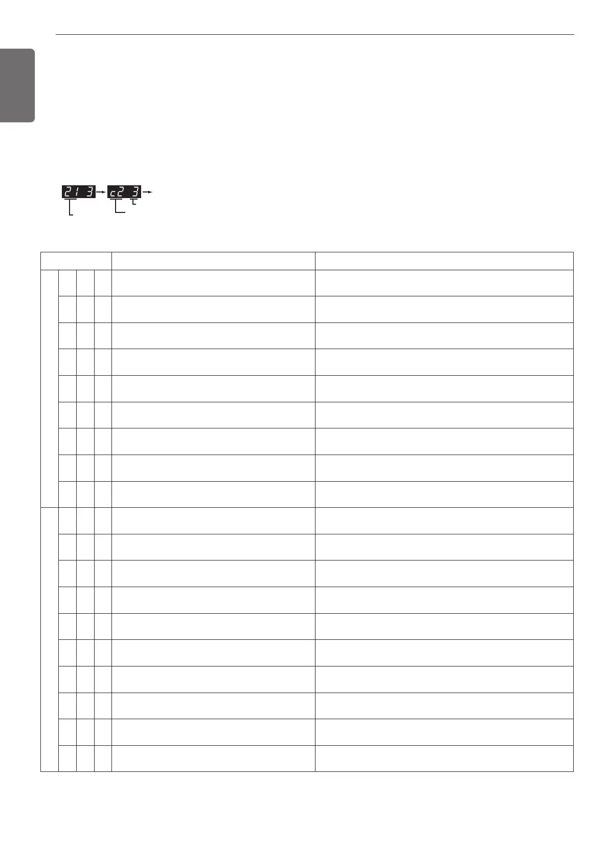
1st,2nd,3rd LED of 7-segment indicates error number, 4th LED indicates unit number.(* = 1: Master, 2: Slave 1, 3: Slave 2, 4: Slave 3)
Ex)
* Refer to the DX-Venitilation manual for DX-Venitilation error code.
E
rror No. of Compressor
Error No.
Error No. of Unit
Repeat
Display Title Cause of Error
Indoor unit related error
0 1 - Air temperature sensor of indoor unit Air temperature sensor of indoor unit is open or short
0 2 - Inlet pipe temperature sensor of indoor unit Inlet pipe temperature sensor of indoor unit is open or short
0 3 -
Communication error : wired remote controller ↔
indoor unit
Failing to receive wired remote controller signal in indoor unit PCB
0 4 - Drain pump Malfunction of drain pump
0 5 -
Communication error : outdoor unit ↔ indoor unit
Failing to receive outdoor unit signal in indoor unit PCB
0 6 - Outlet pipe temperature sensor of indoor unit Outlet pipe temperature sensor of indoor unit is open or short
0 9 - Indoor EEPROM Error
In case when the serial number marked on EEPROM of
Indoor unit is 0 or FFFFFF
1 0 - Poor fan motor operation
Disconnecting the fan motor connector / Failure of indoor
fan motor lock
1 7 - Inlet Air temperature sensor of FAU Air temperature sensor of indoor unit is open or short
Outdoor unit related error
2 1 *
Master Outdoor Unit Inverter Compressor IPM Fault
Master Outdoor Unit Inverter Compressor Drive IPM Fault
2 2 *
Inverter Board Input Over Current(RMS) of Master
Outdoor Unit
Master Outdoor Unit Inverter Board Input Current excess (RMS)
2 3 *
Master Outdoor Unit Inverter Compressor DC link
Low Voltage
DC charging is not performed at Master Outdoor Unit after start-
ing relay turn on.
2 4 * Master Outdoor Unit High Pressure Switch
System is turned off by Master Outdoor Unit high pressure switch.
2 5 *
Master Outdoor Unit Input Voltage High/ Low Voltage
Master Outdoor Unit input voltage is over 487V or below 270V
26*
Master Outdoor Unit Inverter Compressor Start
Failure
The First Start Failure by Master Outdoor Unit Inverter Compres-
sor Abnormality
29*
Master Outdoor Unit Inverter Compressor Over
Current
Master Outdoor Unit Inverter Compressor Fault OR Drive Fault
32*
Master Outdoor Unit Inverter Compressor1 High
Discharge Temperature
Master Outdoor Unit Inverter Compressor1 High Discharge Tem-
perature
33*
Master Outdoor Unit Inverter Compressor2 High
Discharge Temperature
Master Outdoor Unit Inverter Compressor2 High Discharge Tem-
perature
34*High Pressure of Master Outdoor Unit High Pressure of Master Outdoor Unit
 Loading...

