27
ENGLISH
• Initial display order
• Master Unit • Slave Unit
Dip switch setting Dip switch setting ODU Setting
Slave 1
Slave 2
Slave 3
[Heat Pump (Main PCB)]
DIP-SWITCH 7 - Segment
SW01C ( : confirm)
SW02C (ඔ : backward)
SW03C (ඖ : forward)
SW04C (
: cancel)
SW01D (reset)
CAUTION
• In replacement of the indoor unit PCB, always perform Automatic
addressing setting again (At that time, please check about using
Independent power module to any indoor unit.)
•
If power supply is not applied to the indoor unit, operation error occur.
• Automatic Addressing is only possible on the master Unit.
• Automatic Addressing has to be performed after 3 minutes to im-
prove communication.
!
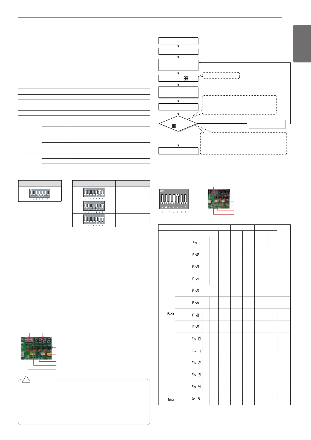
The Procedure of Automatic Addressing
• Automatic addressing setting end
Numbers of indoor unit connection set whose
addressing is completed are indicated for 30seconds
on 7-segment LED after completing setting
Indoor address number is displayed on wired remote control or
indoor unit display window. It is not an error message, will
disappeared when on/off button is pressed on remote control
ex) Display of 01, 02, ..., 15 means connection of 15 indoor units
and Automatic addressing is completed normally.
Automatic addressing start
Waiting 3 minutes
Power On
Press RED Button for 5 s
(SW01C)
7-segment LED = 88
Don’t press RED Button
(SW01C)
Waiting about 2~7 minutes
7-segment LED
OK
YES
NO Check the connections
of communication cable
= 88
* Functions save in EEPROM will be kept continuously, though the
system power was reset.
Setting the function
Select the mode/function/option/value using ‘▶’, ‘◀’ Button and con-
firm that using the ‘●’ button after dip switch No.5 is turned on.
DIP-SW01 7 - Segment
SW01C ( : confirm)
SW02C (ඔ : backward)
SW03C (ඖ : forward)
SW04C (
: cancel)
SW01D (reset)
Order No Mean
①
8~22 Master model capacity
②
10~22 Slave 1 model capacity
③
10~22 Slave 2 model capacity
④
10~22 Slave 3 model capacity
⑤
8~88 Total capacity
⑥
1 Cooling Only
2 Heat Pump
3 Heat Recovery
⑦
38 380 V model
46 460 V model
22 220 V model
⑧
1 LTE
2 LTS / LTN
9 LLS / LLN
Mode
Function Option Value Action
Remarks
Content
Display1
Content
Display2
Content Display3 Content Display4
Implement
Display5
Installation
Cool & Heat
Selector
oFF
op1
~op2
Selected
the
option
- -
Change
the set
value
blank
save in
EEPROM
Static pres-
sure com-
pensation
oFF
op1
~op3
Selected
the
option
- -
Change
the set
value
blank
save in
EEPROM
Night low
noise
oFF
op1
~op15
Selected
the
option
- -
Change
the set
value
blank
save in
EEPROM
Overall de-
frost
on oFF
Selected
the
option
- -
Always
Overrall
defrost on
blank
Save in
EEPROM
ODU ad-
dress
- - 0~254
set the
value
Change
the set
value
blank
Save in
EEPROM
Snow re-
moval &
rapid defrost
oFF
op1
~op3
Selected
the
option
- -
Change
the set
value
blank
Save in
EEPROM
Target pres-
sure auto ad-
justing
oFF
op1
~op6
Selected
the
option
- -
Change
the set
value
blank
Save in
EEPROM
High Effi-
ciency
Cooling
oFF on
Selected
the
option
- -
Change
the set
value
blank
Save in
EEPROM
Auto dust
removal
oFF on
Selected
the
option
--
Change
the set
value
blank
Save in
EEPROM
Low ambi-
ent kit
oFF on
Selected
the
option
--
Change
the set
value
blank
Save in
EEPROM
Compressor
Frequency
Limitation
oFF
op1
~op9
Selected
the
option
--
Change
the set
value
blank
Save in
EEPROM
ODU fan
Limitation
oFF
op1
~op7
Selected
the
option
--
Change
the set
value
blank
Save in
EEPROM
Smart Load
Control
oFF
op1
~op3
Selected
the
option
--
Change
the set
value
blank
Save in
EEPROM
SVC
Comfort
Cooling
oFF
op1
~op3
---
Change
the set
value
blank
-
Automatic Addressing
The address of indoor units would be set by Automatic Addressing
- Wait for 3 minutes after supplying power.
(Master and Slave outdoor units, indoor units)
- Press RED button of the outdoor units for 5 seconds. (SW01C)
- A “88” is indicated on 7-segment LED of the outdoor unit PCB.
- For completing addressing, 2~7 minutes are required depending on
numbers of connected indoor units
-
Numbers of connected indoor units whose addressing is completed are
indicated for 30 seconds on 7-segment LED of the outdoor unit PCB
- After completing addressing, address of each indoor unit is indicated
on the wired remote control display window.
(CH01, CH02, CH03, ……, CH06 : Indicated as numbers of connected
indoor units)
Checking the setting of outdoor units
Checking according to dip switch setting
- You can check the setting values of the Master outdoor unit from the
7 segment LED. The dip switch setting should be changed when the
power is OFF.
Checking the initial display
The number is sequentially appeared at the 7 segment in 5 seconds after
applying the power. This number represents the setting condition.
 Loading...

