30
ENGLISH
Example) Group number setting
1
st
number indicate the group number
2nd number point out indoor unit number
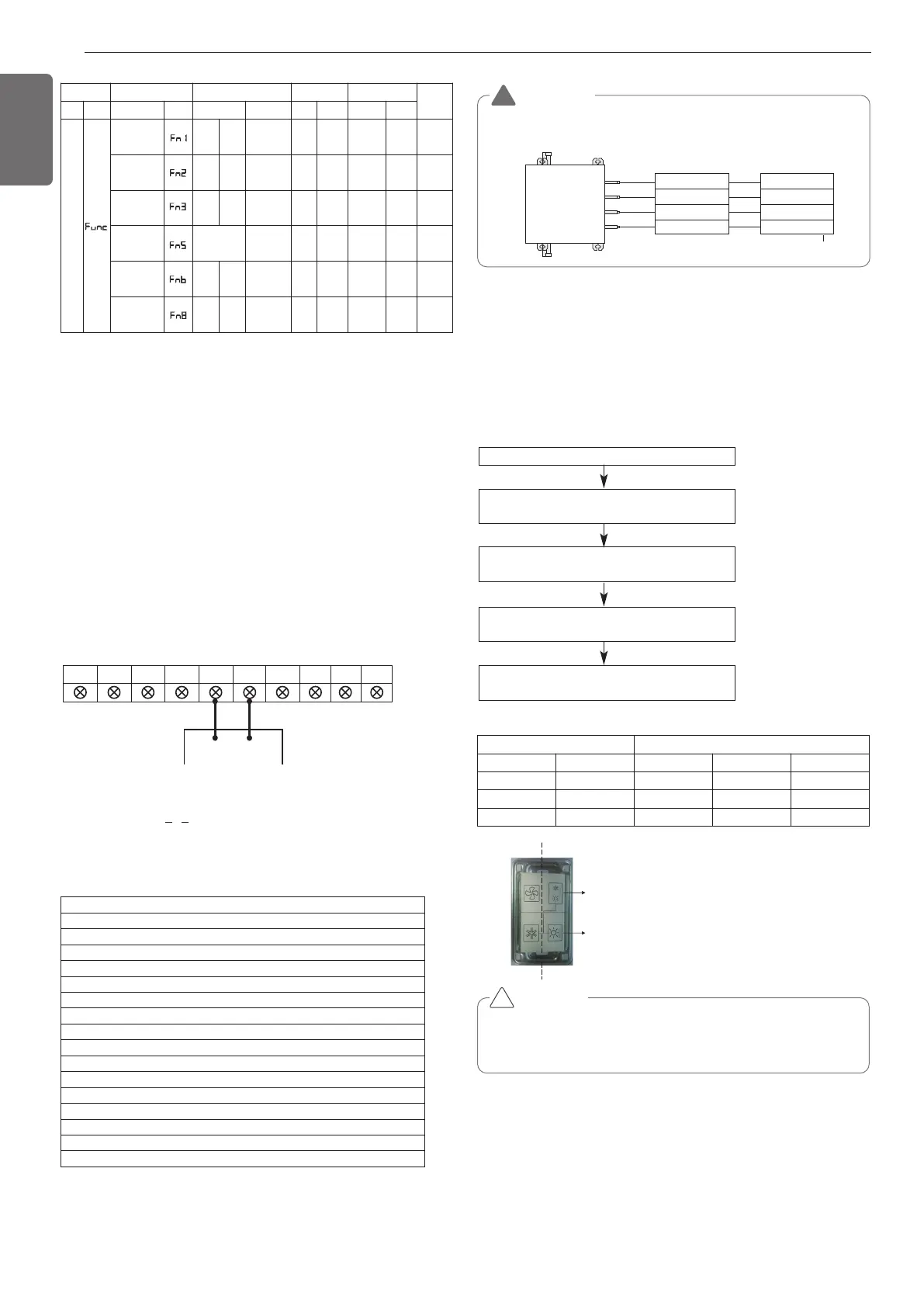
ODU.B ODU.A IDU.B IDU.A CEN.B CEN.A DRY1 DRY2 GND 12V
B(D) A(C)
1 F
Group Indoor unit
Group recognizing the central controller
No.0 group (00~0F)
No.1 group (10~1F)
No.2 group (20~2F)
No.3 group (30~3F)
No.4 group (40~4F)
No.5 group (50~5F)
No.6 group (60~6F)
No.7 group (70~7F)
No.8 group (80~8F)
No.9 group (90~9F)
No. A group (A0~AF)
No. B group (B0~BF)
No. C group (C0~CF)
No. D group (D0~DF)
No. E group (E0~EF)
No. F group (F0~FF)
Mode Function Option Value Action
Remarks
Content
Display1
Content
Display2
Content Display3
Content Display4
Implement Display5
Cool & Heat
Selector
oFF
op1~
op2
Selected
the option
- -
Change
the set
value
Blank
Save in
EEPROM
Static pres-
sure com-
pensation
oFF
op1~
op3
Selected
the option
- -
Change
the set
value
Blank
Save in
EEPROM
Night low
noise
oFF
op1~o
p12
Selected
the option
- -
Change
the set
value
Blank
Save in
EEPROM
ODU
address
-
-
0~255
set
the
value
Change
the set
value
Blank
Save in
EEPROM
Snow re-
moval &
rapid defrost
oFF
op1~
op3
Selected
the option
- -
Change
the set
value
Blank
Save in
EEPROM
Target
pressure
adjusting
oFF
op1~
op3
Selected
the option
- -
Change
the set
value
Blank
Save in
EEPROM
Valve (04)
EX)
Valve (03)
Valve (02)
Valve (01)
Indoor unit (04)
Indoor unit (03)
Indoor unit (02)
Indoor unit (01)
Central control address
HR unit
WARNING
• Valve address and central control address of its corresponding indoor
unit should be set identical in manual addressing.
!
TEST RUN
Cool & Heat selector
Mode setting method
Service PCB DIP switch on : No.5
Select the mode using ‘▶’, ‘◀’ Button :
“Func” Push the ‘●’ button
Select the Function using ‘▶’, ‘◀’ Button :
“Fn1” Push the ‘●’ button
Select the Option using ‘▶’, ‘◀’ Button :
“oFF”,“op1”,“op2” Push the ‘●’ button
Cool & Heat Selection mode is set
Function setting
Switch control Function
Switch(TOP) Switch(Bottom)
oFF op1(mode) op2(mode)
Right Left Not operate Cooling Cooling
Right Right Not operate Heating Heating
Left - Not operate Fan mode Off
CAUTION
• Ask an authorized technician to setting a function.
• If do not use a function, set an off-mode.
• If use a function, first install a Cool & Heat selector.
!
Switch (TOP)
Switch (Bottom)
Left side
Right side
* Functions save in EEPROM will be kept continuously, though the
system power was reset.
* Dip switch 3 can be OFF except when installing the only 4 series in-
door units (named ARNU***4).
Group Number setting
Group Number setting for Indoor Units
- Confirm the power of whole system(Indoor Unit, Outdoor Unit) is
OFF, otherwise turn off.
- The communication cables connected to CEN.A and CEN.B terminal
should be connected to central control of Outdoor Unit with care for
their polarity (A-A, B-B ).
- Turn the whole system on.
- Set the group and Indoor Unit number with a wired remote control.
- To control several sets of Indoor Units into a group, set the group ID
from 0 to F for this purpose.
Outdoor Units (Main PCB)
Installation
1,MFL69717904,영영 18. 8. 29. 영영 2:50 Page 30

 Loading...