28
ENGLISH
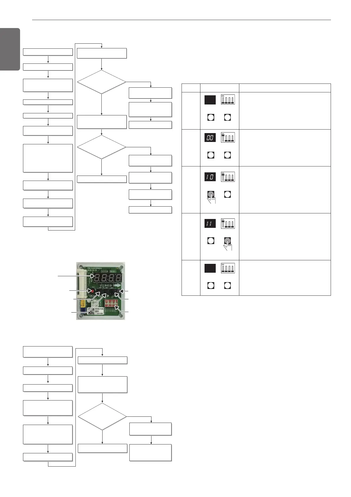
Flow chart of auto addressing for pipe detection
Completion of auto pipe detection
Are the number
of indoor units connected to the
outdoor unit wiring and displayed
one equal?
Reset the power of HR unit PCB
Confirm that the setting of No.2, 3 of
SW02E corresponds with the number of
indoor units.
Master unit PCB DIP switch on : No.5
Select the mode using ‘ȯ’, ‘ȭ’ Button :
“Idu” Push the ‘Ɨ’ button
Select the mode using ‘ȯ’, ‘ȭ’ Button :
“Idu” Push the ‘Ɨ’ button
Select the “Id 6” function using ‘ȯ’, ‘ȭ’
Button :“StA” Push the ‘Ɨ’ button
Select the “Id 5” function using ‘ȯ’, ‘ȭ’
Button :“Ath” or ”Atc” Push the ‘Ɨ’
button.
Outdoor temperature is over 15°C(59°F) :
“Ath” Using
Outdoor temperature is below 15°C(59°F) :
“Atc” Using
88' is displayed on 7-SEG of the outdoor
unit main PCB
Outdoor unit is operated for 5~60 minutes.
The number of indoor units detected is
displayed for 30 seconds on the outdoor
unit PCB after outdoor unit stopped
Display error on outdoor unit PCB
Display error on HR unit PCB
Outdoor unit PCB : HR
⇒
HR unit
number
⇒
Valve number
HR unit : '200'
Check the HR unit and indoor unit
Pipe detection error occur after 30
seconds.
Check the installation of pipe of
outdoor, indoor, HR unit
Incompletion of auto pipe detection
Retry auto pipe detection after
checking trouble
Is the pipe
setting condition
satisfied during the operation of
indoor unit?
Confirmation of indoor unit address setting
Turn No.1 of SW02E of HR unit PCB off.
NO
NO
YES
YES
※It is possible to be generated mode changing noise of heating and
cooling which is normal. There is no mode changing noise at normal
operation.
DIP-SWITCH
SW01D(reset)
SW04C(x:cancel)
7-Segment
SW03C(▶:forward)
SW02C(◀:backward)
SW01C(●:confirm)
Flow chart of manual addressing for pipe detection
Completion of manual pipe detection
Reset the power of HR unit PCB.
Enter the central control address into
each indoor unit using its wired remote
control.
On the HR unit PCB, manually set address
of each valve of the HR unit to the central
control address of the indoor unit
connected to the valve.
Reset the power of outdoor unit PCB.
Wait for about 5 minutes.
The number of the indoor units installed is
displayed.
Ex)HR
⇒
The number of the indoor
Check the central control address of
indoor and HR unit.
Make sure that reset the outdoor
unit power when changing the
central control unit
Are the number
of indoor units connected to the
outdoor unit and displayed one
equal?
Execute in case of Auto pipe detection
failure
Turn No.1 of SW02E of HR unit PCB on.
NO
YES
Example of manual valve addressing (Non-
Zoning setting)
(In case that an indoor unit of central control address "11" is connected
to a valve #1 of an HR unit)
- Prerequisite for manual valve addressing: central control address of
each indoor unit must be preset differently at its wired remote con-
trol.
- Above setup must be done for all HR unit valves.
- The valve that is not connected with any indoor unit should be ad-
dressed with any other number than used address numbers of the
valves connected with indoor units.
(The valves does not work if the address numbers are same.)
Example of manual valve addressing (Zoning
setting)
(In case that an indoor unit of central control address “11”, “12” is
connected to a valve #1 of an HR unit)
Zoning control is connecting 2 or more indoor units at one pipe of HR
unit. In case of Zoning control, in order to set controls with multiple in-
door units connection uses the rotary switch. Namely, only the rotary
switch changes from same valve set condition and set indoor units
connection.
1) On dip switch of the corresponding valves and sets the rotary
switch at 0.
2) Setting the number with tact switch.
3) In case of addition of indoor units to same port, increases 1 with the
rotary switch and sets number with tact switch.
4) In case of checking the number which the corresponding valve is
stored, turn on dip switch and set the number of rotary switch.
5) Indoor units set available 8 per a port(rotary switch 0~7), in case of
setting above of 8 with rotary switch, it will display error.
6) Setting the rotary switch on original condition(HR unit number set
conditions) after all finishing a piping setting.
No.Display and setup Setup and Contents
1
- Operation: None
- Display: None
2
- Operation: Turn dip S/W No.1 on to ad-
dress valve #1
- Display: Existing value saved in EEP-
ROM is displayed in
7-SEG.
3
- Operation: Set the digit of 10 to the
number in Group High data of the wired
remote control connected to the corre-
sponding indoor unit to the valve #1 by
pressing left tack S/W.
- Display: Digit increasing with the times
of pressing tack S/W is displayed in left
7-SEG
4
- Operation: Set the digit of 1 to the num-
ber in Group Low data of the wired re-
mote control connected to the
corresponding indoor unit to the valve
#1 by pressing right tack S/W.
- Display: Digit increasing with the times
of pressing tack S/W is displayed in right
7-SEG
5
- Operation: Turn dip S/W No.1 off to save
the address of
valve #1
- Display: "11" displayed in 7-SEG disap-
pears
1,MFL69717904,영영 18. 8. 29. 영영 2:50 Page 28

 Loading...