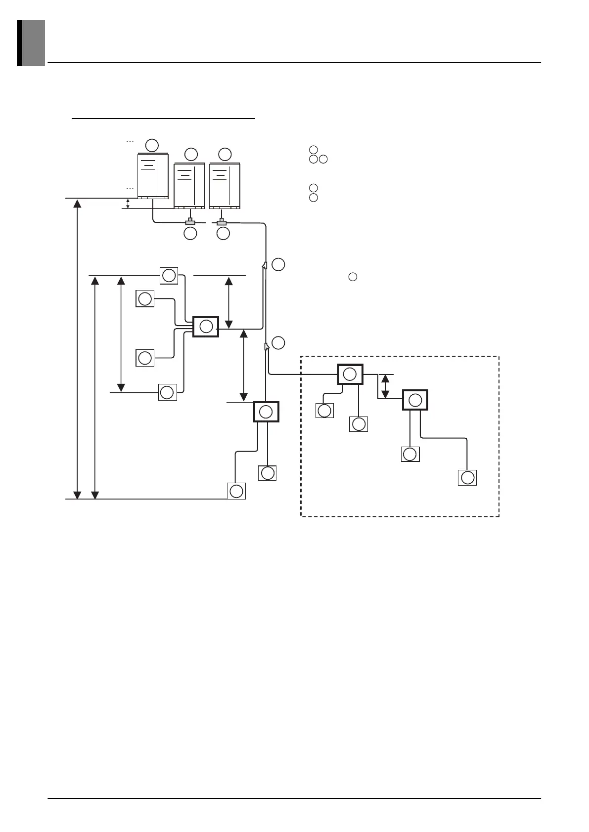
Example : 10 Indoor Units connected
Aircooled / Watercooled VRF Unit
Y Branch / Header / HR Unit
!! After Header,
HR unit or Branch pipe can not be used.
Indoor Units
Connection branch pipe between Outdoor/Outside units
A Main pipe before 1st Branch
E,F Branch pipe between Unit
B,C,D Branch pipe between branch to branch
a,b,c,d,e,f,g,i,j,k
Indoor Unit connecting pipe
In case of = HR unit
“a” Height if HR unit is installed with Y branch.
“b” Height in serial connection of HR units.
e.g farthest indoor unit
A
B C
D
E
• It is recommended that difference in length of the pipes connected to the indoor units (a~k) is minimized.
The large difference in pipe lengths, the more different performance between indoor units.
• *** Serial connection of HR units : Capacity sum of indoor units ≤ 230 kBtu/hr
If the large capacity indoor units (Over 5 HP; using overØ15.88/Ø9.52) are installed, it should be used the Valve
Group setting.
4. Refrigerant Piping System
 Loading...