HR1
48k 48k
1 2
HR2
48k 48k
3 4
B
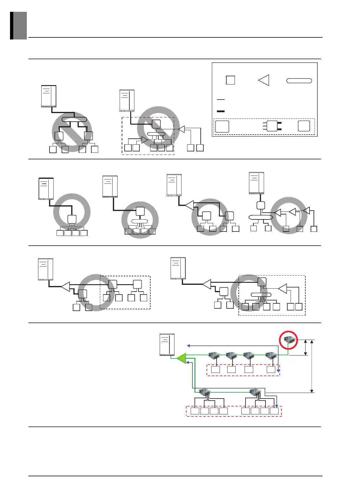
• Impossible installation
: Head branch pipe → HR unit
Pattern 1
Outdoor unit
Outside unit
HR1
1 2 3 4 5 6 7
7k 7k 7k 24k 24k
7k 7k
• Impossible installation
: HR unit → Y Branch and Header
→ Y Branch after Header
B
A
Pattern 2
Pattern 3
HR1
54k 54k 54k 54k
1 2 3 4
Pattern 4
15k 15k 15k 15k
1 2 3 4
HR1
B
Pattern 5
HR1
48k 48k
A
1 2
HR2
48k 48k
3 4
HR1
B
Pattern 6
A
A
A
1 2 3 4 5
24k 24k 12k 12k 24k
Pattern 7
HR1
A
48k 48k
1 2
HR2
54k 54k
3 4
HR3
54k 54k
5 6
*
Pattern 8
A
A
HR1
48k 48k
1 2
HR2
*
B
12k 12k 12k 12k
3 4 5 6
24k
7
24k
8
• Pipe installation from outdoor units to HR units
: 3 pipes
(Low pressure Gas pipe, High pressure Gas pipe, Liquid pipe)
• Pipe installation from HR units to indoor units
: 2 pipes
(Gas pipe, Liquid pipe)
B
A
1
HR1
Outdoor
Unit
Low pressure Gas pipe
High pressure Gas pipe
Liquid pipe
Gas pipe
Liquid pipe
Indoor
Unit
Piping of HR unit
Symbols
Indoor Unit Y Branch pipe Header Branch pipe
5m(16ft)
30m(98.4ft)
1) under 40m(131ft)
Keep the sum of indoor capacity under 69.5kW(230 kBtu/h).
Indoor
Unit
Indoor
Unit
Indoor
Unit
Indoor
Unit
Indoor
Unit
Indoor
Unit
Indoor
Unit
Indoor
Unit
Indoor
Unit
Indoor
Unit
Indoor
Unit
Indoor
Unit
1) under 40m(131ft)
Y branch
Keep the sum of indoor capacity under 69.5kW(230 kBtu/h).
Installation Example
• The maximum total capacity of each branch
pipe of HR unit is 17.5kW(60 kBtu/h).
• If a indoor unit capacity over that, two
neighboring outlets of one HR unit should be
linked by Y branch pipe and connected to
one indoor unit.
(Large capacity(76kBtu/h and 96kBtu/h unit)
• The maximum total capacity of indoor units
is 69.5kW(230 kBtu/h).
• * : Serial connection of HR units
: Capacity sum of indoor units ≤ 230 kBtu/h
: Maximum indoor units per a branch are 8 indoor units
Connective Capacity Limit
※ This figure is representative. Actual appearance of unit may be
different by product type, but schematic diagram will stay same.
4. Refrigerant Piping System
 Loading...