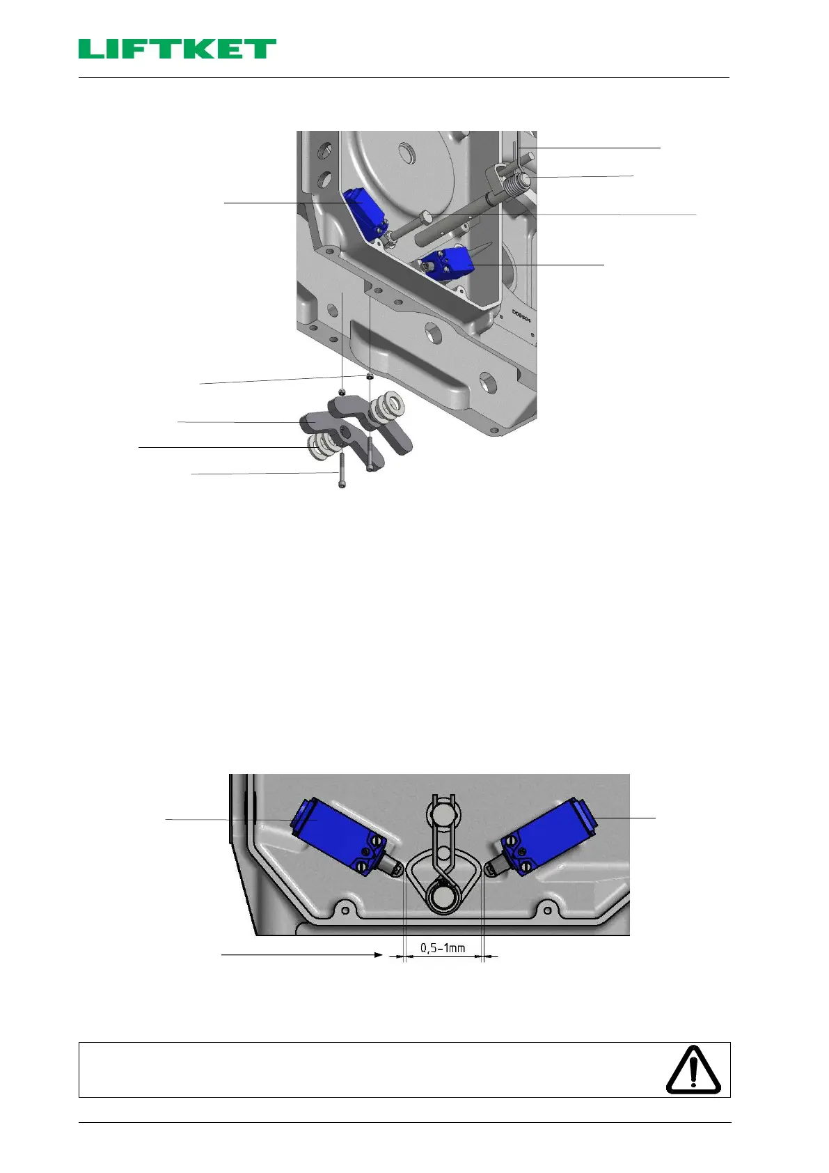
Diagram No 27: Disassembling and assembling the limit switch shaft
Disassembling the limit switch shaft
1. Release the two M5x45 screws of the limit switch lever.
2. Pull the complete limit switch shaft together with the spiral spring through the head of the anvil.
3. Remove the limit switch shaft together with the spiral spring, while catching the limit switch levers and washers
that fall out.
Assembling the limit switch shaft
1. Assemble in the reverse order.
2. Following the assembly of the limit switch shaft the distance between the position switch and the limit switch cam
must be between 0.5 mm and 1.0 mm.
Upon first use do not forget to cross-check the symbols shown on the control
pendant with the direction of hook travel, and check whether or not the lifting motion
is safely stopped by the corresponding limit switch.
 Loading...