44
10.3 Slipping clutch
10.3.1 Brake operation
The patented safety slipping clutch is located between the drive gear and the brake. The brake acts directly on the
load via the gearbox with a form-locking connection, without loading the clutch. Even with heavier wear of the clutch
the load cannot lower in an uncontrolled way, because the brake holds the load whatever its position. The slipping
clutch acts as a dry clutch, using asbestos free linings.
The slipping clutch is a directly acting lifting force limitation that cannot be used
operationally.
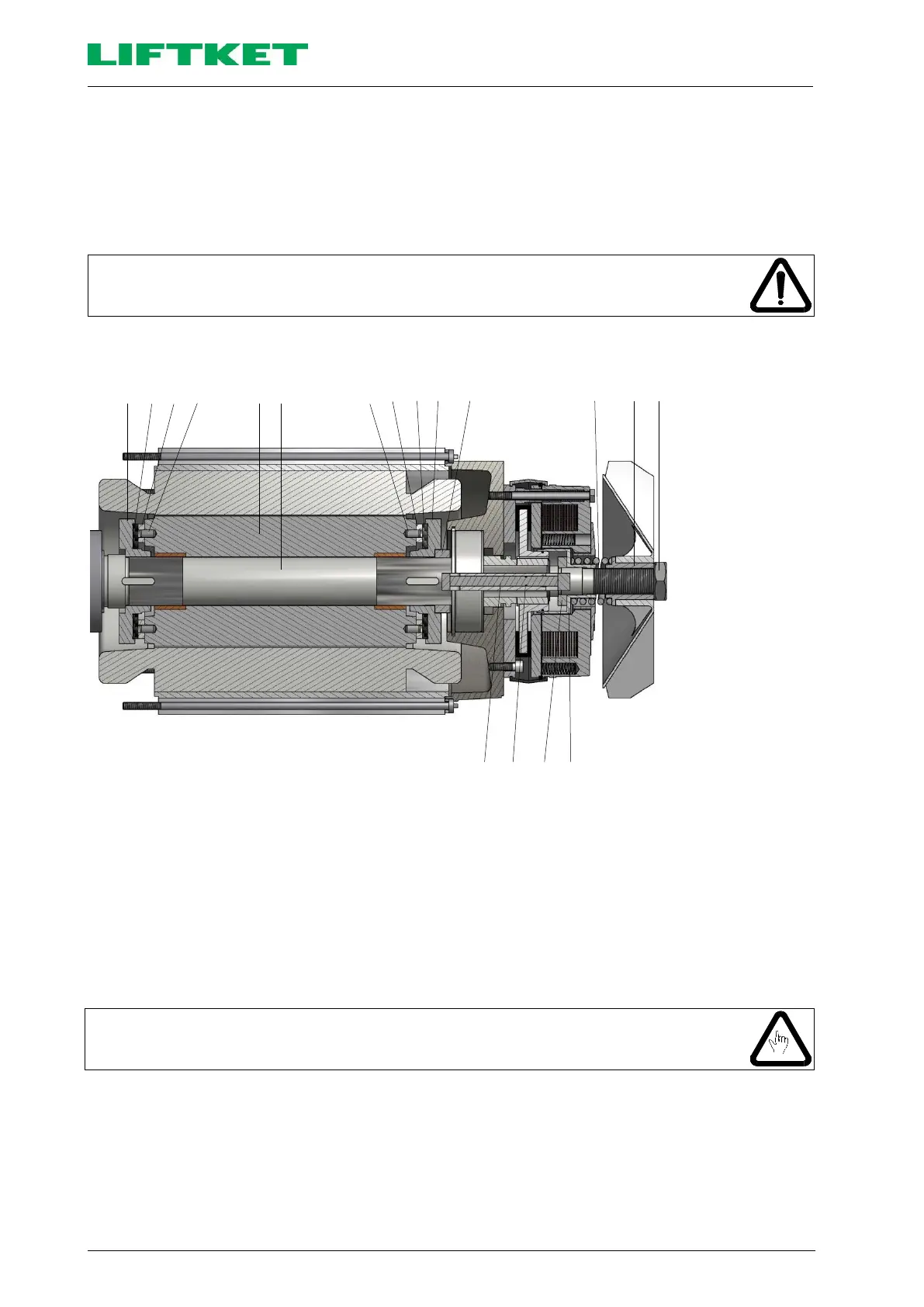
4 5 6 7 9 8 7 6 5 4 11 3 2 1
1
2
3
4
5
6
7
8
9
10
11
12
13
14
Lock nut
Fan with the
threaded bush
Pressure
springs
Clutch hub
Clutch disks
Clutch linings
Stud bolts
Motor drive
shaft
Rotor
Pressure bush
Pressure ring 1
Pressure ring 2
Packing ring
Pressure bolt
Diagram No 35: Sliding clutch sectional view
The parts of the slipping clutch: two clutch hubs (4), located on both sides of the motor rotor (9) that are connected to
the motor drive shaft (8) in a form-locking fashion, the clutch linings (6), the clutch discs (5) that are bolted with the
rotor (9). The motor shaft (8) carries the pressure ring 1 (11), the internal pressure bolt (14) with the packing ring (13),
the pressure ring 2 (12), the pressure bush (10) the pressure spring (3), the fan with the threaded bush (2) and with
the lock nut (1).
10.3.3 Slipping clutch adjustment
If the load is measured with a crane scale or an adjustment device against a fixed
fixation point, then the load value being read with a slipping clutch is 30% higher than
the nominal value setting. The slipping time of the clutch may not exceed 2-3 seconds.
1. Unscrew the lock nut (1).
2. With feeling tighten the pressure spring (3) by turning the fan with the threaded bush (2) so that the hoist just
about lifts the load.
Turning the fan with the threaded bush (2) to the right the torque of the clutch will increase.
Turning the fan with the threaded bush (2) to the left the torque of the clutch will reduce.
3. Fix the setting of the fan with the threaded bush using the lock nut (1).
4. Verify again the setting of the clutch by lifting the nominal load until the upper hook position.
 Loading...