Manual F5021B - Shaft selection
5.Shaft selection
The shaft selection consists of a incremental encoder and
solenoid switches, respectiveley sensors.
The incremental encoder optinally is positioned on the
engine or in the shaft.
Especially for rope lifts it is used the encoder of the
engine, which can hand over at the most of the frequency
inverters via encoder output (encoder simulation) to the
controller.
In this case it is entered the effectiv datas for the
parameters F6 (nominal speed), F7 (engine speed) and F8
(encoder release).
For slowly running synchronous motors it mostly have to
be juggeled with the parameters nominal-rotation-speed
and encounter-puls-rate. E.g. 150U/min at 2048ppr
changed to 600U/min (*4) and 512 ppr.
If the encoder is assembled in the shaft (rotating string) for
the nominal-rotation-speed have to be entered an
equivalence-rotation-speed (equates encoder-rotation-
speed).
For the system used by us with carbon cord show up the
following values:
(F7) 0,8 1 1,2 1,4 1,6 m/s
(F8) 294 367 441 514 588 RPM
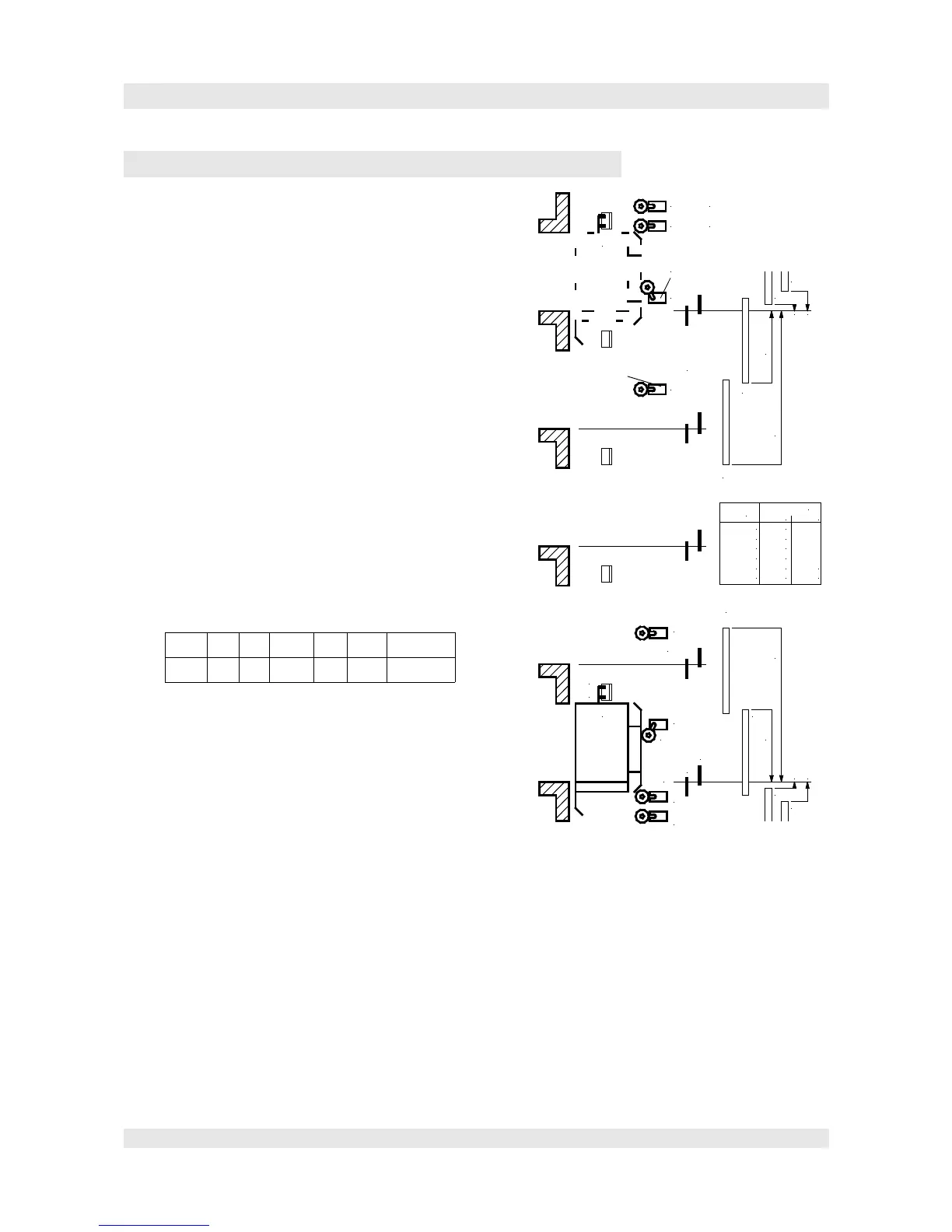
re-levelling sensors:
As the shaft selection is done with the engine encoder, the slip of the tractions sheave have to be
compensated. For this, there are in every floor re-levelling-plates installed with about 220mm length. (The
Page 21
Car
Car
C
D
C
D
KO1
KO
IEO
NEO (Emergency stop TOP)
(Inspection stop TOP)
(Downslow switch TOP)
Downslow switch v>2.5m/s
KO1
only if v>2.5m/s
KO
IEO
NEO
KU1
v>2.5m/s
KU
IEU
NEU
KU1
KU
Inspection switch
DOWN
EmergencyStop
DOWN
Downslow switch v>2,5m/s
Downslow switch
DOWN
IEU
L.KO
L.KO1
L.IEO
L.NEO
L.KU
L.KU1
L.IEU
L.NEU
0,63m/s:
1,0m/s:
1,6m/s:
1,8m/s:
2,0m/s:
2,5m/s:
950
1300
2400
2600
2400
2400
v
Distance (mm)
L.KO
3800
5600
L.KO1
 Loading...