Manual F5021B - SM01 F5021 main board
6.SM01 F5021 main board
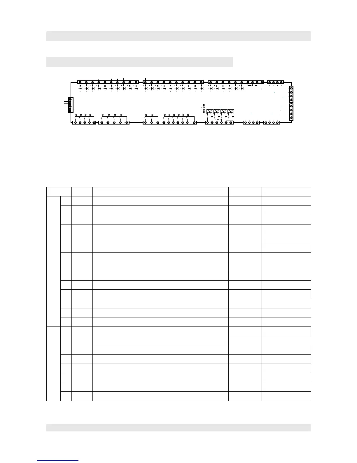
SM01 F5021 Mainboard Terminals
Configuration of inputs and outputs:
The in- and outputs are limited free configurable. The following table shows the basic settings which are
ok in the most of cases. Some signals have a different configuration in some special cases. These specials
you can find in the electrical drawing of each case. Thus significant is the electrical drawing.
SM01 terminals:
Terminal Name Description Function Advise
JP1 1 X0 Signal inspection on, respectively normal operation input N
2 X1 Inspection/return motion up input N
3 X2 Inspection/return motion down input N
4 X3 Delay switch upwards/above for v>2,5m/s,
at short stop in the upmost stop.
input N F24=5
Counting impulse B (hydraulic lift with magnet switch) F24=3
5 X4 Delay switch downwards for v>2,5m/s,
at short floor in the lowest stop.
input N F24=5
Counting impulse A (hydraulic lift with magnet switc) F24=3
6 X5 learn trip -end-switch upwards/top input N
7 X6 learn trip -end-switch downwards/down input N
8 X7 Delay switch upwards/top input N
9 X8 Delay switch downwards/down input N
10 X9 re-levelling upwards (levelled) input N
1 X10 re-levelling upwards (levelled) input N
2 X11 Converter error signal or ready signal input N Rope lift
Monitoring approval-relay of the downwards valve Hydraulic lift
3 X12 Firedepartement-controlling on input N
4 X13 Fire stop 1 input N
5 X14 Fire stop 2 input N
6 X15 Motor contactor K1 Monitoring input N
7 X16 Motor contactor K2 Monitoring input N
Page 25
1 2 3 4 5 6 7 8 9 10
JP1
X0 X1 X2 X3 X4 X5 X6 X7 X8 X9
1 2 3 4 5 6 7 8 9 10
1 2 3 4 5 6 7 8 9 10
JP2
X10 X11 X12 X13 X14 X15 X16 X17 X18 X19
2011 12 13 14 15 16 17 18 19
1 2 3 4 5 6 7 8 9 10
JP3
X20 X21 X22 X23 X24 X25
21 22 23 24 25 26
1 2 3 4 1 2 3 4 5
JP9
Y0 Y1 Y2 Y3 Y4 Y5 Y6 Y7
D1 D2 D3 D4 D5 D6 D7 D8
1 2 3 4 5 6 7 8 9 10
JP11
Y8 Y9 Y10 Y11 Y12 Y13 Y14 Y15
D9 D10
D11 D12 D13 D14 D15 D16
1 2 3 4 5 6
JP12
JP6
1234
Speed 0-10V
0V(AGND)
1 2 3 4
1234
JP4
JP5
TXA+
TXA-
TXV-
TXV+
TXA+
TXA-
TXV-
TXV+
JP20
1
2
3
4
5
6
0V
0V
+5V
+24V
0V
0V
200
100
2 3 4
JP8
V+:15V
V-: 0V
A>
B>
1
normal/inspection
manual up
limit switch up (learn trip)
limit switch down (learn trip)
slow down switch up
slow down switch down
up levelling
down levelling
fire return home
error inverter
contactor monitoring
motor contactor 1
analog output
encoder input
speed governor
inputs 230VAC
see LED X26,X27,X28,29
5
FireStop1
FireStop2
automatic
evacuation
manual down
up limit switch (v>2m/s)
down limit switch (v>2m/s)
Autotuning is active
contactor monitoring
brake contactor
monitoring safety circuit
inverter RUN
motor temperature
shutdown
brake closed
brake monitoring
brake opened
brake abrasion
monitoring
CAN1
(car, shaft)
CAN 2
(group)
X26
X27
X28
X29
JP10
2 3 4
JP7
B-
B+
A-
A+
1
encoder input
sym.
X26 X27 X28 X29
 Loading...