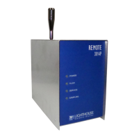
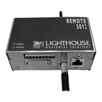
Lighthouse REMOTE 2014P, 3014P, 5014P Operating Manual
3-6 248083408-1 Rev 1
WARNING:
Contact
Lighthouse Technical
Support for the correct
instrument configuration
BEFORE attempting to use
RS485 COM mode with a
PC. Failure to heed this
warning can result in
damage to PC, instrument
or both.
For detailed description of the MODBUS registers and commands,
please see “MODBUS Register Map v1.48” on page A-1.
4-20mA Analog Inputs
This REMOTE instrument has two 4-20mA analog inputs that can be
fitted with up to four 4-20mA environmental sensor. Lighthouse
provides optional environmental sensors: Temperature/Relative
Humidity (T/RH), Air Velocity (AV), Differential Pressure (DP).
Analog Sensors
The Sensors are connected to the instrument with RJ-12 cables. The
pinout of the cables is shown below:
Lighthouse sensors come complete with adapters and prewired cables.
The Lighthouse Temperature/Relative Humidity sensor has both
functions wired to the same connector. Plug the connector into the port
labeled “1”.
Note:
Changes to the
analog configuration will
change historical
environmental values in
the data buffer.
Each port can be used for one dual-channel or two single-channel 4-
20mA sensors (when wired correctly), two devices total per port. When
each port is connected to two single-channel analog sensors, a total of
four analog sensors can be connected to the REMOTE. Otherwise, only
one single-channel or one dual-channel device may be used at a time on
each port. Please contact Lighthouse for additional information about
converters and wiring.
Table 3-1 Analog Connector Pinout
Pin Number Function
15VDC
2 Analog #1 In
3 24VDC (VCC)
4 GND (tied to Pin 6)
5 Analog #2 In
6 GND