7
1. Overview 2. Setup & Use
3. Optional
Accessories
4. Troubleshooting
5. Warranty, Safety
& Specifications
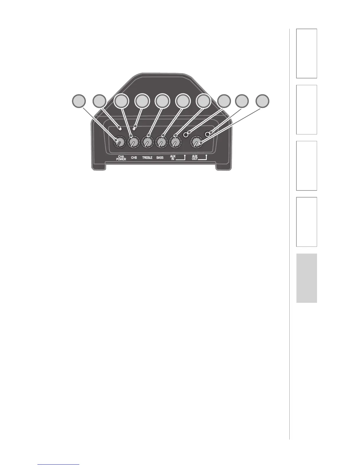
TOP PANEL CONTROLS
1. CH A POWER: This knob turns on
the power for the 705iR and
controls the channel A volume. We
recommend using channel A if you
are using a single microphone for
your system.
2. LED LIGHT: Located above the
CH A POWER knob. Turns red
momentarily when the system
power is turned on.
NOTE: When a transmitter/
microphone set to channel A is
turned on, the channel A LED
glows green to indicate your
transmitter’s signal is being
received by the amplifier.
3. CH B VOLUME: This knob
controls the volume for channel
B. You must first turn the 705iR
on with the CH A POWER knob,
then turn the CH B VOLUME knob
clock-wise to increase volume. Use
channel B when using a second
microphone.
4. LED LIGHT: Loacted above CH
B VOLUME knob. Turns green to
indicate a signal is being received
from a microphone/transmitter set
to channel B.
5. TREBLE: This knob controls the
high-frequency sound of the 705iR.
6. BASS: This knob controls the low-
frequency sound of the 705iR.
7. AUX IN VOLUME: This knob
controls the volume level of an
external audio source (computer,
iPod, CD player) that is plugged
into the AUX IN jack.
8. AUX INPUT JACK: This 3.5 mm
jack is used to connect to an
external audio source.
9. AUX OUTPUT JACK: This jack
sends audio to external equipment
such as an assistive listening
device (Personal FM System) or
recording device.
10. AUX OUT VOLUME: This knob
controls the audio level going to
external equipment when plugged
into the AUX OUT jack.
1 2 3 4 5 6 7 8 9 10