Suzhou Lily Tech. Co., Ltd.
Page 5. Total 5 pages
4. Press
〖
▲
〗
and
〖
▼
〗
to set U74.
5. Press〖P〗to start AT.
During AT, the room temperature (PV) will reach and vibrate around SP for several times. Then the PID parameters will be
calculated, and display will be off.
If AT fails, it will show the reason of failure: “At1”, “At2”, “At3”, and “At4”, see: Display->Text.
If AT is successful, display “SUc”. New PID parameters will be get. Press any key, “SUc” disappears, start PID control.
If AT never be successful, and never fails, because the PV can not never reach SP, set big power rate, or with a bigger
heater.
If AT has lasted 180 minutes, and has not finished, stop AT, display “At4”.
Note
There are some notes for PID AT in ZL-7817A manual.
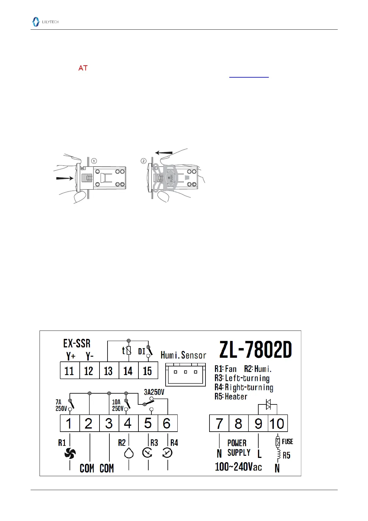
Installation
1. Insert the controller into hole 2. Slide the bracket to fix the device (step two)
Warning
If the temperature heater power rate is big, or has inductance such as coil wired heater, use external SSR-DA, instead of
integrated SSR.
If other loads are big, or with capacitance or inductance, such as many humidifiers, we advise to use intermediate relay,
SSR-AA, or magnetic contactor.
When wiring the controller, do not supply power.
Overload damage is not within warranty.
Attention
Electrical wiring must be manipulated by certified electrician.
Connect according to electrical wiring diagram. Wrong connection will damage the device.
Do not layout the sensor bundle together with power supply bundle.
Avoid working in erosive, wet and strong electrical-magnetic field environment.
This device has been checked fully before shipment. The warranty time is one year, damaged by wrong usage, such as
wrong connection, is not warranted.
Wiring Diagram