Page 21 of 36
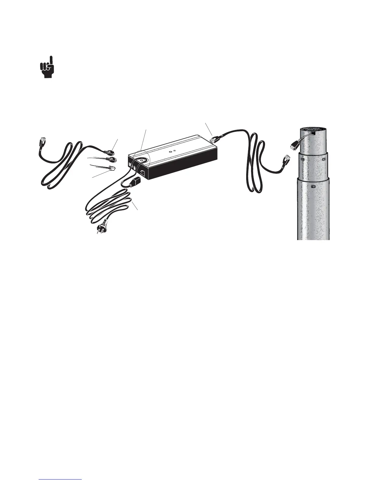
Figure 7
Electrical connection of the DB/DL system
The DB/DL system is to be connected as shown on figure 7. The DB/DL is to be connected to the sockets on the control box by
means of the motor cables, which have a 6-pin plug in each end.
Finally, the mains cable is to be mounted and power switched on. Please note that the control box must only be
connected to the voltage stated on the label.
DP
DL/DB
Cable relief
Mains cable
DL/DB