14
LINCE ITALIA S.p.A.
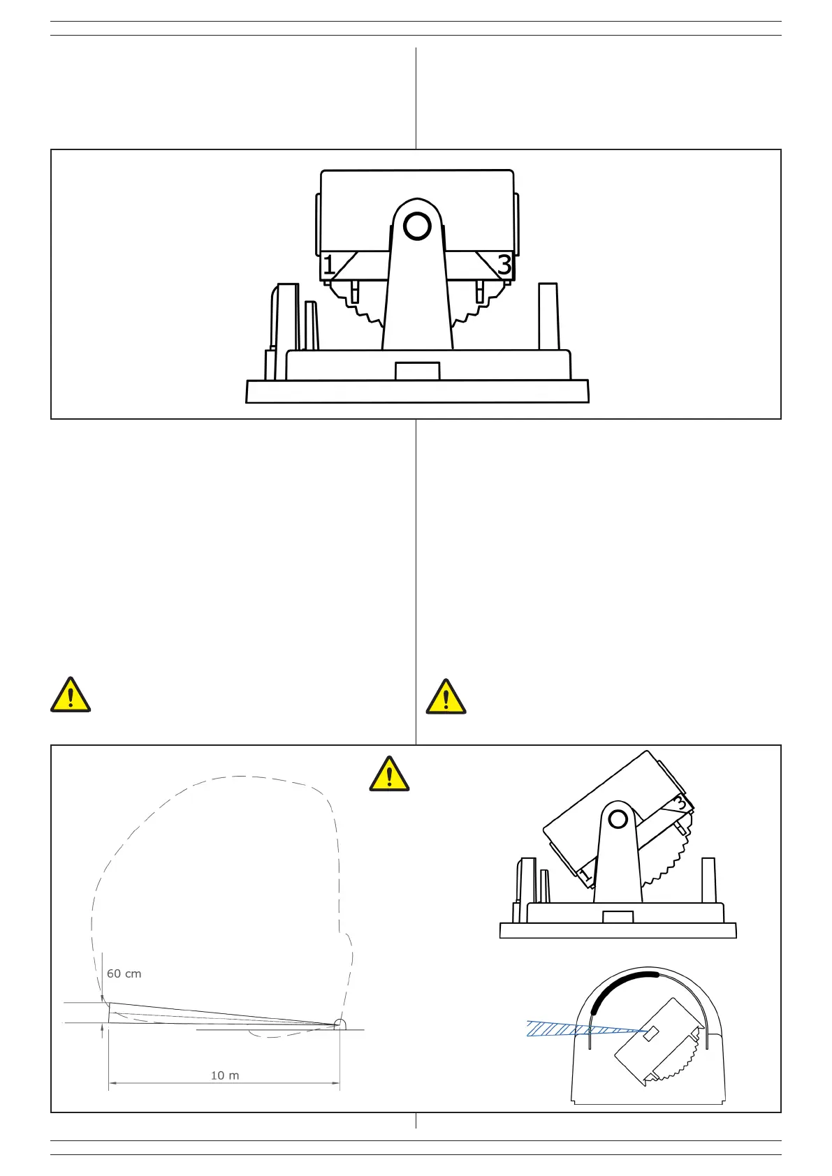
Fig. 25
Le combinazioni riportate successivamente della posizione della
maschera e della meccanica interna permettono di coprire tutte
le esigenze installative riportate in precedenza.
Per ogni installazione viene riportato anche come si posizionano
sia i fasci IR che la microonda (area tratteggiata); quest’ultima
è disponibile solo per il 1908-BOBBY-AM-T. Nelle prossime
immagini la posizione della maschera è rappresentata da una
linea più spessa.
3.1 CONFIGURAZIONE 1 - FASCIO SINISTRO
Nella prima congurazione viene utilizzato solo un fascio verso
sinistra, viene ottenuta ruotando la meccanica basculante
in posizione 1 e facendo scivolare la copertura sulla lente in
posizione B.
La meccanica interna presenta in alto l’indicazione delle tre
posizioni in cui è possibile ruotarla al ne di venire in contro alle
esigenze installative. Per portare la meccanica in posizione 1 da
posizione 2 (centrale) ruotarla facendole compiere 5 scatti verso
sinistra; per portarla in posizione 3 farle compiere 5 scatti verso
destra.
The internal mechanic parts reports on the top an indication of
the three positions where it is possible to rotate it in order to
comply with the installation requirements.
To bring the mechanical part from position 2 (central) to position
1 rotate fulll 5 shots to the left; to bring them in position 3 fulll
5 shots to the right.
The combinations listed subsequently of the position of the mask
and the internal mechanical parts allow to cover all installation
requirements listed above.
For each installation is also reported how placing both the IR
beams and microwave (dotted area); this last feature is only
available only for 1908-BOBBY-AM-T. in the next images the
mask position is represented by a thicker line.
3.1 CONFIGURATION 1 - LEFT BEAM
In the rst conguration is used only a beam towards the left, it
is obtained by rotating the tilting mechanism in position 1 and by
sliding the cover on the lens in position B.
Fig. 26
NO AM
POS. B
NOTA:
In questa congurazione il sistema antimascheramento
non è utilizzabile.
NOTE:
In this conguration, the anti-masking system is not
usable.