15
LINCE ITALIA S.p.A.
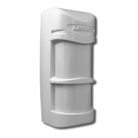
Fig. 27
3.2 CONFIGURAZIONE 2 - FASCI SINISTRO E
CENTRALE
Nella seconda congurazione vengono utilizzati due fasci
orientati verso sinistra e a 90° tra di loro. Viene ottenuta ruotando
la meccanica basculante in posizione 1 e facendo scivolare la
copertura sulla lente in posizione D.
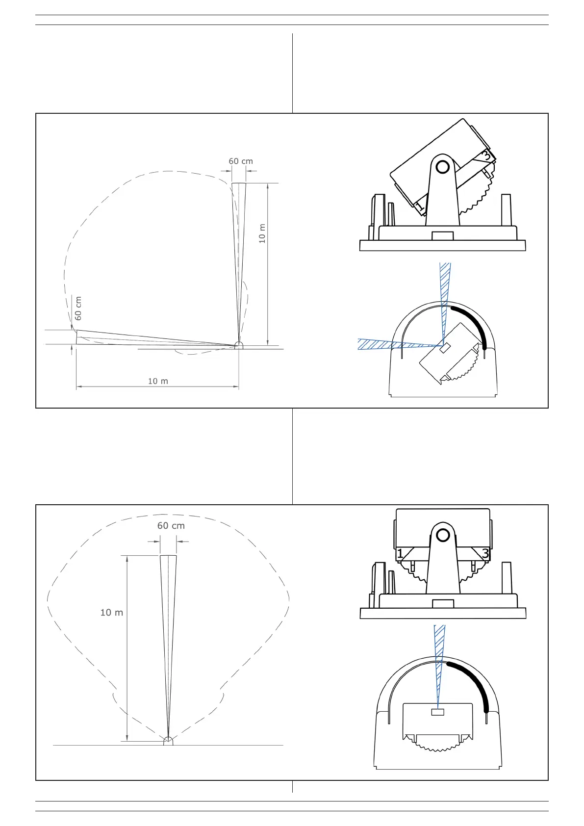
Fig. 28
3.3 CONFIGURAZIONE 3 - FASCIO CENTRALE
Nella terza congurazione viene utilizzato solo un fascio frontale
e perpendicolare alla parete di installazione. Viene ottenuto
ruotando la meccanica basculante in posizione 2 e facendo
scivolare la copertura sulla lente in posizione D.
POS. D
POS. D
3.2 CONFIGURATION 2 - LEFT AND ENTRAL BEAMS
In the second conguration are used two beams oriented to the
left and at 90 ° between them. It is obtained by rotating the tilting
mechanism in position 1 and by sliding the cover on the lens in
position D.
3.3 CONFIGURATION 3 - CENTRAL BEAM
In the third conguration it is used only a front beam and
perpendicular to the installation wall. It is obtained by rotating the
tilting mechanism in position 2 and by sliding the cover on the
lens in position D.