Return to Section TOC Return to Section TOC Return to Section TOC Return to Section TOC
Return to Master TOC Return to Master TOC Return to Master TOC Return to Master TOC
TROUBLESHOOTING & REPAIR
F-74 F-74
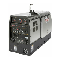
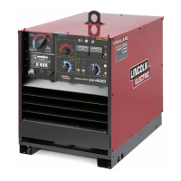
COMMANDER 400
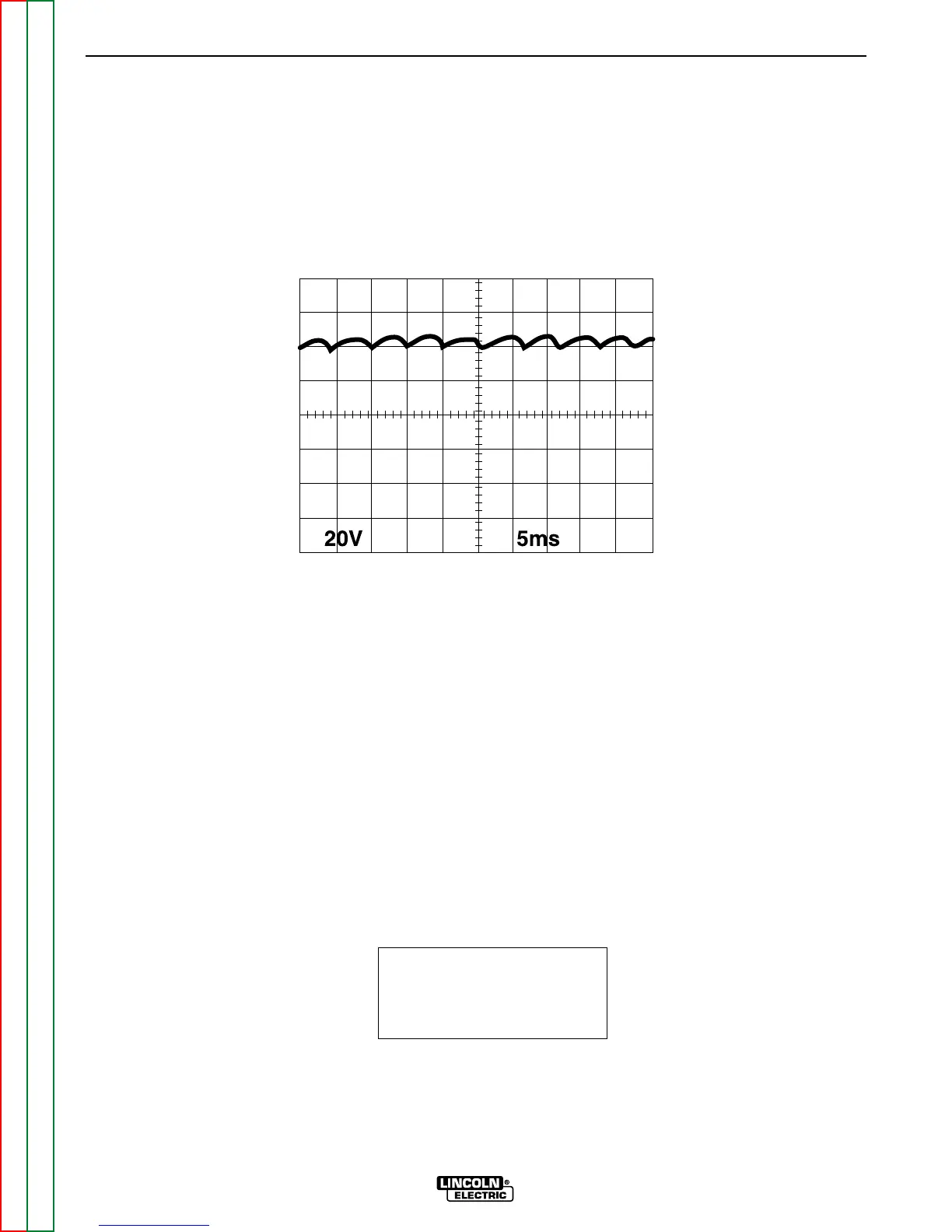
This is the typical DC output voltage
generated from a properly operating
machine. Note that each vertical
division represents 20 volts and that
each horizontal division represents 5
milliseconds in time.
The machine was loaded with a
resistance grid bank to 400 amps at
40 volts.
Note: Scope probes connected at
“STICK” welding output terminals.
SCOPE SETTINGS
Volts/Div.....................20V/Div.
Horizontal Sweep.....5 ms/Div.
Coupling.............................DC
Trigger.........................Internal
NORMAL WELD VOLTAGE WAVEFORM (STICK CC)
MACHINE LOADED TO 400AMPS AT 40 VOLTS
0 volts
 Loading...