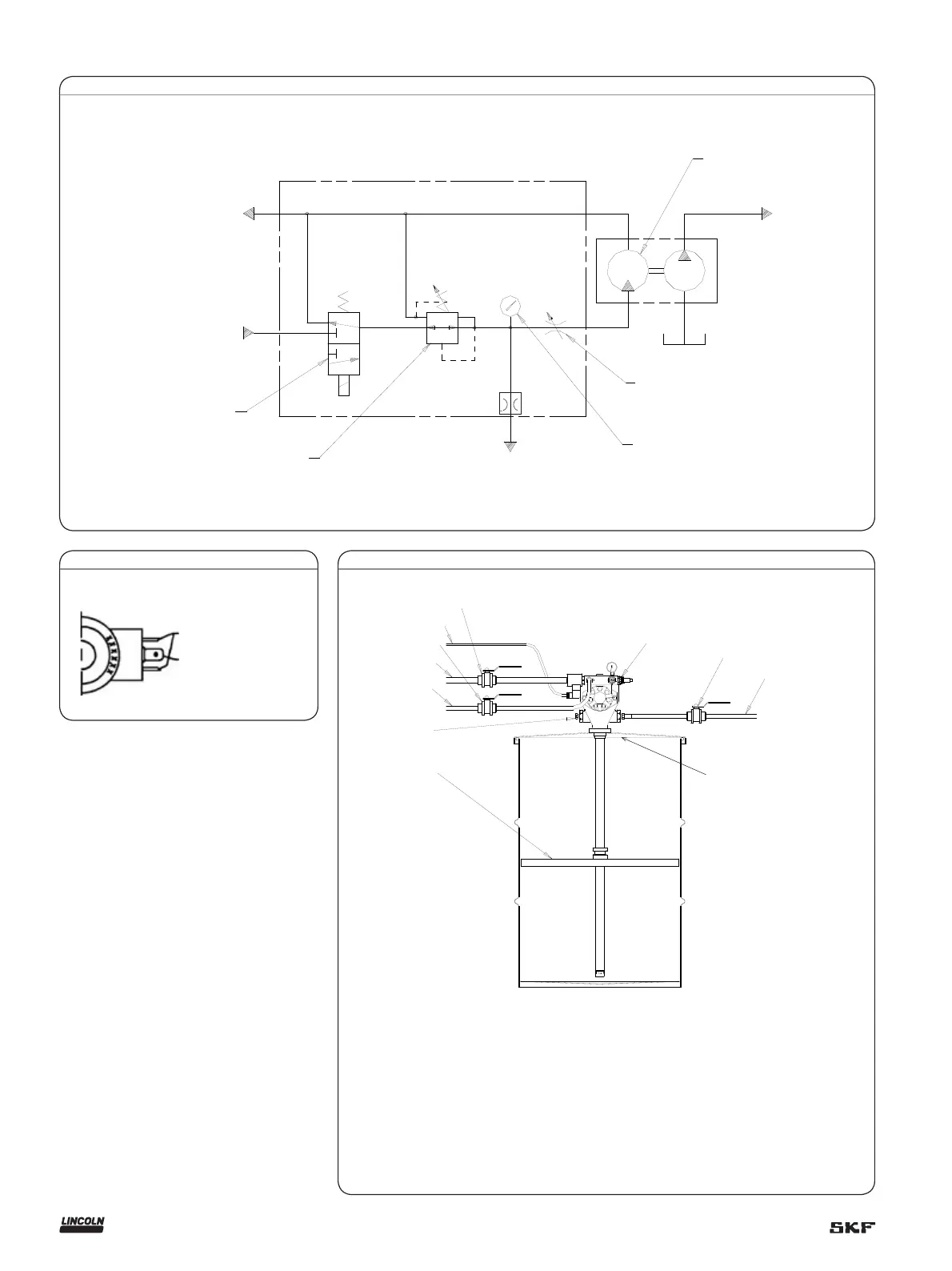
Fig. 3
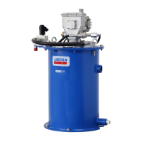
Fig. 1
Schematic
Hydraulic fluid
inlet
Hydraulic fluid
return to tank
Solenoid valve
( 34 and 35)
Pressure reducing
valve (38)
Vent
Valve
Pressure gauge
(Item 32)
Flow control valve (39)
Hydraulic motor (42)
Material
outlet
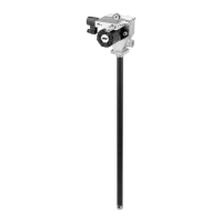
Fig. 2
Solenoid valve
24V DC connections
No connection to
center lug
A
F
G
H
J
B
D
E
C
K
L
A - Pump outlet plug
B - Hydraulic supply line
C - Hydraulic return to tank line (
3
/4 in. ID min.)
D - Supply line shut-off valve
E - 24 V DC from controller
F - Return line shut-off valve (
3
/4 in. ID min.)
G - Vent valve port with restrictor
H- Outlet shut-off valve
J - Material supply line
K - Follower plate (85492 for 120 lb. drum only)
L - Drum cover (83115 for 400 lbs., 84616 For 120 lbs.)
4
To order call 1-800-548-1191 or visit www.partdeal.com - info@partdeal.com
 Loading...