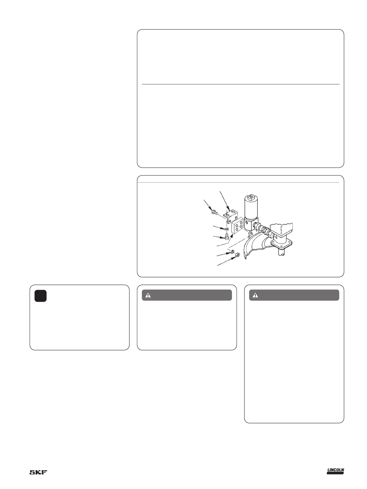
Fig. 4
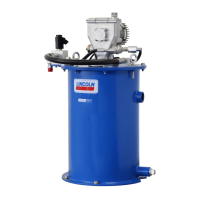
Installing the pump
Typical installation is shown only as a guide
for selecting and installing system compo-
nents. Contact your Lincoln
Industrial representative for assistance
in designing a system to suit your spe-
cic needs.
The pump was tested in lightweight oil
which was left in to protect the pump from
corrosion. Flush the pump before connect-
ing it to the system to prevent contamina-
tion of the grease with residual oil.
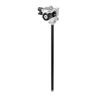
The pump has flow and pressure controls
integrated into the manifold (76). A normally
closed on/off Solenoid Valve (74) is also in-
tegrated into the manifold and will start or
stop the pump operation.
1 Mount the pump securely on the drum
cover so that it cannot move or vibrate
during operation.
2 Attach hydraulic supply line to the Inlet
and return line to the tank ports.
3 Connect material supply line to the pump
outlet. Plug the unused outlet on opposite
side of the pump.
4 Install high pressure shut-off valve in the
material supply line (required)
5 Connect 24 V DC power supply to the
solenoid valve (74) († fig. 1).
Use connector plug (75) supplied with the
pump.
!
Notice
To install the pump model 85481
as a replacement pump for 84961 used
on model 84944, use adapter/spacer kit
P/N 272013 with bolts P/N 50014,
included in the pump package († fig. 4).
Hydraulic pump performance specifications
Test conducted with Alvania NLGI #2 grease
Grease output (in.³/min. [cm³/min.]),
1,000 psi (69 bar) back pressure
Hydraulic flow input
Temperature
°F (°C)
1 gal./min
(4 l/min.)
2 gal./min.
(8 l/min)
3 gal./min.
(11 l/min.)
4 gal./min.
(15 l/min.)
5 gal./min
(19 l/min.)
6 gal./min.
(23 l/min.)
7 gal./min.
(26 l/min.)
80 (27) 7 (115) 14 (229) 21 (344) 28 (459) 34 (557) 40 (656) 45 (737)
40 (4) 7 (115) 14 (229) 21 (344) 28 (459) 33 (541) 39 (623) 41 (642)
20 (-7) 6 (98) 13 (213) 17 (279) 22 (361) 28 (459) 32 (594) 36 (590)
0 (-18) 6 (98) 11 (180) 15 (245) 19 (310) 23 (376) 27 (442) 30 (491)
-10 (-23) 5 (82) 7 (115) 8 (131) 9 (148) 10 (164) 12 (197) 13 (213)
-20 (-29) 4 (66) 6 (98) 8 (131) 10 (164) 12 (197) 14 (229) 15 (245)
Solenoid valve with manual override standard on Model 85247, 85670 and 85675 optional on other models.
361104
50014
1)
66246
1)
50034
1)
249616
1)
66246
51026
1)
Included in spacer kit 272013
Mount the pump securely on the drum
cover. Failure to do so could result in
personal injury and equipment damage.
WARNING
Do not exceed 450 psi (32 bar) working
hydraulic pressure. Use high pressure
components to reduce risk of serious in-
jury including fluid injection and splash-
ing in the eyes or on the skin. All acces-
sories connected to the pump outlet
must have at least 5,000 psi (350 bar)
minimum hydraulic operating pressure.
All accessories connected to the pump
inlet must have at least 3,500 psi
(241 bar) minimum working pressure.
WARNING
5
To order call 1-800-548-1191 or visit www.partdeal.com - info@partdeal.com
 Loading...