Inspection
If over pressurizing of the equipment is
believed to have occurred, contact the fac-
tory authorized warranty and service center
nearest you for inspection of the pump.
Specialized equipment and knowledge is
required for repair of this pump. Contact the
factory authorized warranty and service
center nearest you for repair or adjustments
other than maintenance specified in this
manual.
Annual inspection by the factory author-
ized warranty and service center nearest
you is recommended.
A list of factory authorized warranty and
service centres is available upon request.
Damaged pumps
Any pump that appears to be damaged in
any way, is badly worn or operates abnor-
mally, shall be removed from use until
repairs are made. Contact the factory
authorized warranty and service center
nearest to you for repairs.
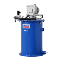
Description
A newer version of the FlowMaster pump
was introduced in July of 2008. These units
incorporate the following improvements:
• Bushing & plunger seals used along with
elastomer cup seals for longer life and
better high temperature operation.
• A crankcase oil dipstick
• Hardened and ground section on the re-
ciprocating tube for longer life and better
crankcase oil control.
• Hardened and ground pivot pin bushings
with a tighter fit into the pivot pin anchor.
• Improved pivot pin fastener with deeper
allen hex socket.
All of the improved parts can be used with
the older model pumps, so the upgraded
parts and subassemblies will now be
supplied to repair older model pumps.
Please see the Maintenance and repair
section, page 9 for a list of the new repair
kits and their proper application.
• 85480 - Pump for 120 pound drum
(16 gallon)
• 85481 - Pump for 60 pound drum
• 85482 - Pump for 400 pound drum
(55 gallon)
• 85483 - Pump for 5 gallon pail
• 274055 - Same as 85481 with solenoid
cable assembly
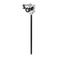
General description
During the down stroke, the pump cylinder
is extended into the grease. Through the
combination of shovel action and vacuum
generated in the pump cylinder chamber,
the grease is forced into the pump cylinder.
Simultaneously, grease is discharged
through the outlet of the pump. The volume
of grease during intake is twice the amount
of grease output during one cycle. During
the upstroke, the inlet check closes, and one
half of the grease taken in during the previ-
ous stroke is transferred through the outlet
check and discharged to the outlet port.
Typical output of the pump is shown
on page 5.
Appropriate use
• All pump models are exclusively designed
to pump and dispense lubricants using
hydraulic power.
• The maximum specification ratings
should not be exceeded.
• Any other use not in accordance with in-
structions will result in loss of claims for
warranty and liability.
• Do not exceed 3,500 psi (241 bar) maxi-
mum supply inlet hydraulic pressure.
Exceeding the rated pressure may result
in damage to system components and
personal injury.
Pump performance and specification
Supply inlet hydraulic pressure, maximum) 3,500 psi (241 bar)
Operating working hydraulic pressure 300 to 450 psi (20 to 32 bar)
Hydraulic inlet flow Up to 7 gal/min. (28 l/min.)
Pump ratio with manifold 9:1 at low inlet pressure (300 to 350 psi
(20 to 25 bar)) and low inlet flow (below 2 gpm
(7 lpm)) Pump ratio approaches 11.0:1 ratio at
higher inlet pressure and flow.
Operating temperature -20 to +150 °F (-29 to 65 °C)
Operating voltage 24 V DC
Hydraulic inlet port SAE 4
Tank return port SAE 6
Pump Outlets 1/4 in. NPTF
Maximum hydraulic fluid temperature 250 °F (121 °C)
Weight 36 lbs. (16 kg)
3
To order call 1-800-548-1191 or visit www.partdeal.com - info@partdeal.com
 Loading...