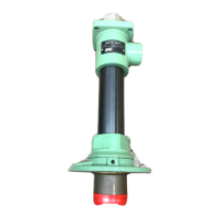
The Lincoln Pile Driver® III Pump Assembly, models 84900, 84901, and 84902 (Series "B"), is a robust, double-acting positive displacement reciprocating pump designed for dispensing various industrial materials. It is engineered to handle sealants, adhesives, inks, and other substances that may dry out or build up on pump components.
Function Description
The primary function of the Pile Driver® III Pump Assembly is to transfer and dispense materials efficiently. As a double-acting pump, it intakes material on both the "up" and "down" strokes, ensuring continuous flow. The pump is designed to operate with an airmotor, which drives the reciprocating action.
A key feature of this pump is its specialized gland packing design, which addresses common issues like material build-up and rapid wear. Externally, a spring-type metal wiper (Item 5) scrapes dried material from the pump plunger before it enters the gland packing. To enhance the wiper's effectiveness, the pump's lube well should be filled with a fluid compatible with the material being pumped. Internally, a Protection Sleeve (Item 9) with concentric grooves creates a labyrinth path, reducing the impact of internal pressure and stroke change-over fluctuations on the gland seal. A second internal wiper further limits the gland seal's exposure to the pumped material. This combination of wipers and the protection sleeve aims to extend gland seal life and prevent leakage.
Important Technical Specifications
The Pile Driver® III Pump Assembly offers various configurations with different pump tubes and airmotors, resulting in a range of performance characteristics.
General Specifications:
- Pump Stroke: 6 inches (152 mm)
- Operating Temperature: -30°F to +160°F (-34°C to +71°C)
- Max. Recommended Speed: 75 Cycles/Minute
- Wetted Part Materials: Carbon steel, Bronze, Polyurethane, Nitrile
- Weight: 56 lbs. (25.4 kg.)
Output per cycle:
- 84900: 22 cu. in. (360 cc)
- 84901: 17 cu. in. (278 cc)
- 84902: 12 cu. in. (196 cc)
Output at 75 cpm:
- 84900: 7.1 gpm (26.9 liter/min)
- 84901: 5.5 gpm (20.8 liter/min)
- 84902: 3.9 gpm (14.8 liter/min)
Model-Specific Performance (examples):
- Model 84900 (Pump Tube 2342, Airmotor 86810): Ratio 42:1, Max Delivery Pressure 4200 psi (290 bar), Max Air Pressure 100 psi (7 bar).
- Model 84901 (Pump Tube 2355, Airmotor 86810): Ratio 55:1, Max Delivery Pressure 5500 psi (379 bar), Max Air Pressure 100 psi (7 bar).
- Model 84902 (Pump Tube 2375, Airmotor 86810): Ratio 75:1, Max Delivery Pressure 7500 psi (517 bar), Max Air Pressure 100 psi (7 bar).
The pump's dimensions vary based on the specific airmotor and pump tube combination. For instance, Dimension "A" (overall height) can range from 39-7/8 inches [1083 mm] to 40-3/4 inches [1105 mm]. Dimension "B" (plunger rod diameter) varies from 1.312 inches [33.3 mm] for model 84902 to 1.625 inches [41.3 mm] for model 84900.
Usage Features
Installation and Operation:
- The pump should be installed upright for operation, preferably as close to the material tank as possible, using a minimum 3-inch (76 mm) I.D. inlet hose or pipe.
- For bulk material dispensing, a Model 83727 Stand Pipe is recommended.
- Airmotor Attachment: The airmotor is securely attached to the pumptube using tie rods and a coupling nut. The process involves hand-tightening components and then slowly cycling the pump with minimal air pressure before final tightening of the nuts.
- Outlet Position Adjustment: The pump outlet's position can be adjusted by loosening three screws (Item 26), rotating the pumptube outlet to the desired position, and then retightening the screws to 25 ft/lbs.
- Pump Priming: To initiate operation, the pump must be primed with the material to be pumped. As a double-acting pump, it intakes material on both strokes. Priming involves opening the output line and slowly opening the air supply valve until the pump cycles slowly, allowing air to be expelled and material to fill the pump and lines. If priming fails, the Bleeder Valve (Item 11) can be slightly opened to expel trapped air.
- Lube Well: The lube well should be filled with a fluid compatible with the pumped material to assist the external metal wiper. However, it should not be filled to full capacity to prevent fluid from being drawn into the airmotor due to reciprocating movement.
Safety Precautions:
- Always read and follow operating instructions, fluid manufacturer's recommendations, and wear protective clothing.
- Do not exceed the maximum working pressure of the pump or any component in the system.
- Never alter or modify any part of the equipment.
- Do not operate with combustible gases or fuels.
- Do not attempt repairs while the system is pressurized.
- Ensure all fluid connections are securely tightened.
- Regularly inspect equipment for wear or damage and replace parts immediately.
- Always check for proper operation and ensure safety devices are in place.
- Static Sparking: Ground the pump, dispensing valve, and containers when handling flammable fluids to prevent fire or explosion. Check electrical continuity with an ohmmeter.
- Fires: Ensure adequate ventilation when pumping volatile solvents and keep them away from heat, sparks, and open flames.
- Material Depletion: Do not allow the pump to operate when out of material.
- Pump Inlet Safety: Keep hands away from the pump inlet when the airline is connected. The pump must be firmly mounted to a Pressure Primer or Standpipe, and the area around the inlet must be clear of obstructions.
- Do not operate the pump continuously at speeds exceeding 75 cycles per minute.
- Disconnect the air line from the pump airmotor during long idle periods.
Maintenance Features
Disassembly and Reassembly:
The manual provides a detailed, step-by-step procedure for disassembling the pump, including specific tools required and the items they are used for. Reassembly is performed by reversing the disassembly procedure, with torque specifications provided for critical components (e.g., Gland Nut, Piston Nut, Bolt Connector).
Key Disassembly Steps Include:
- Removing screws from the mounting flange.
- Removing the mounting flange, priming plug, and connector.
- Removing the priming plunger nut.
- Removing the inlet bushing, check seat, and associated O-rings.
- Removing the bolt connector and coupling nut.
- Removing the priming rod, piston, and plunger assembly, including adapters, keepers, check assembly, retaining rings, guide washers, U-cups, piston nut, check ball, and piston collar.
- Removing the pump tube and its O-rings.
- Removing the bleeder valve.
- Removing the gland nut, wiper, and spacer.
- Removing the bushing, its O-ring, and U-cup.
- Removing the sleeve, scraper, and retaining ring.
Service Kits:
Lincoln offers various service kits to facilitate maintenance and repair:
- Pumptube Seal Kits: Available in Polyurethane, Teflon, and Polyethylene. Polyurethane kits include all soft seals, while Teflon and Polyethylene kits include gland and piston U-cups only.
- Gland Seal Kits: Contain the gland U-cup and O-ring only.
Troubleshooting:
The manual includes a troubleshooting guide to help diagnose common issues:
- Pump does not operate: Check for restricted or inadequate air supply, obstructed material output, or if the pump is not primed.
- Erratic or accelerated operation: May indicate insufficient material supply or material too heavy for priming.
- Pump operates on "down" stroke only (missing "up" stroke): Suggests worn or damaged piston U-cup or piston check.
- Pump operates on "up" stroke only (missing "down" stroke): Points to worn or damaged inlet check or priming rod packing.
- Pump operating but not dispensing material: Could be due to insufficient material supply or an unseated/damaged inlet check.
For all troubleshooting scenarios, the recommended solutions typically involve checking for restrictions, refilling material, priming the pump, or checking and replacing worn/damaged components.
Note: Pumps are factory tested with light oil, which is left in to protect parts during storage. It is recommended to flush the pump before use to prevent material contamination.