1 2
Spring Return
3 Point
0-10VDC
VAV
0-10VDC
From Zone
Smoke
PT 1000
PT 1000
Serial number
12
2022-11-28
lindab | installation
We reserve the right to make changes without prior notice
FireSystemPro Damper unit
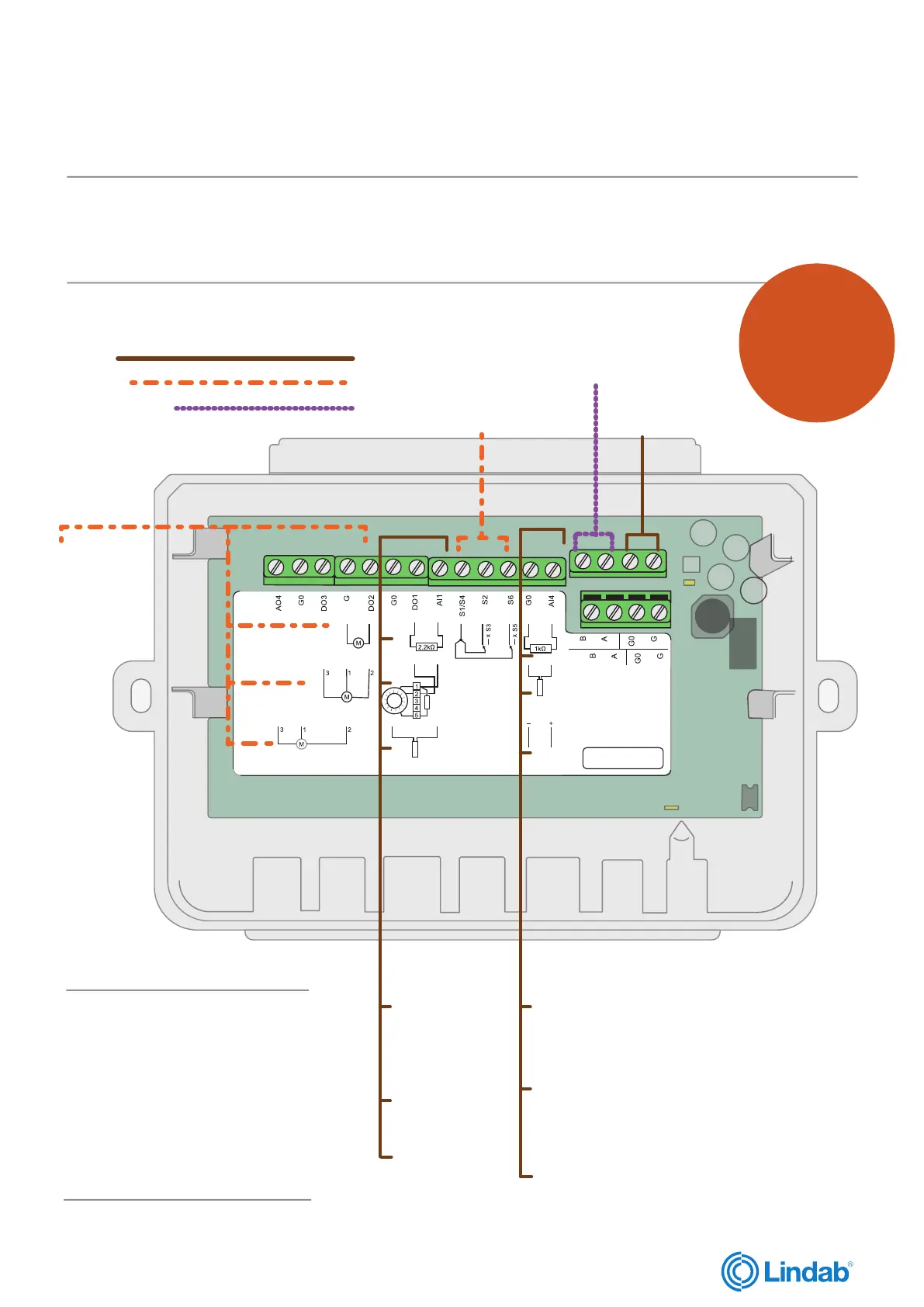
Circuit card overview
Alt. 1
Fire damper
Alt. 2
Smoke control damper
Alt. 3
VAV spring return
Note:
Remove resistor
if alt.1 or alt.2
below is installed
Alt. 1
Smoke detector
Alt. 2
PT1000
End switches
for dampers
Note:
Remove resistor if alt.1 or
alt.2 below is installed
Alt. 1
PT 1000
(Temperature sensor)
Alt. 2
Room regulator
Communication
IN and OUT
POWER 24V
IN and OUT
Input
Damper
Communication
Caution!
Before installation or maintenance, the power supply should first be disconnected. Installation or maintenance of this unit
should only be carried out by qualified personnel. The manufacturer is not responsible for any eventual damage or injury
caused by inadequate skills during installation, or through removal of, or deactivation of any security devices.
Regulators
Choose one alternative
Sensors
Choose one
alternative
(Temperature sensor)
Dampers
Choose one
alternative
Note:
There is no fixed option for connect-
ing the damper unit. The circuit card
overview is only to show what input
each device should be connected to.
Dampers, regulators and sensors
can be connected independently of
each other and the alternatives you
choose.
Click here to
go directly to
the technical
datasheet for
PRO-S


 To Next Page