B
G G0
A N
11 2 2
+C
+C
+C
S1/S4
S1/S4
S2
S2
S6
S6
S1/S4
S2
S6
1 2
GND
SPEED
0-10V
COM
NO
NC
ERROR
EXT RESET
NIGHT MODE
SMOKE DETECTORS
SUM
GDO
COM
COM
AFA
NO
NC
NO
NC
RUN
AHU
1
2
AGND
AGND
PT1000
RUN
SEF
RS485 POWER
DAMPER 1 DAMPER 2
DAMPER 3
B A N
G GO +C
REL1 REL2 REL3
RESET
AGND
AGND
FT
AI1 AI2
JP1
JP7
AI3 AI4 UI1 UI2 UI3 UI4
TST TRIG
FIRE INSP
DI8
Dl7DI7 DI6 DI5 DI4 DI3
DI2 DII D07 D06 D05 D04 D03
D02
D01
GD0
AGND
A01
PCB12377D
5
2022-11-28
lindab | installation
We reserve the right to make changes without prior notice
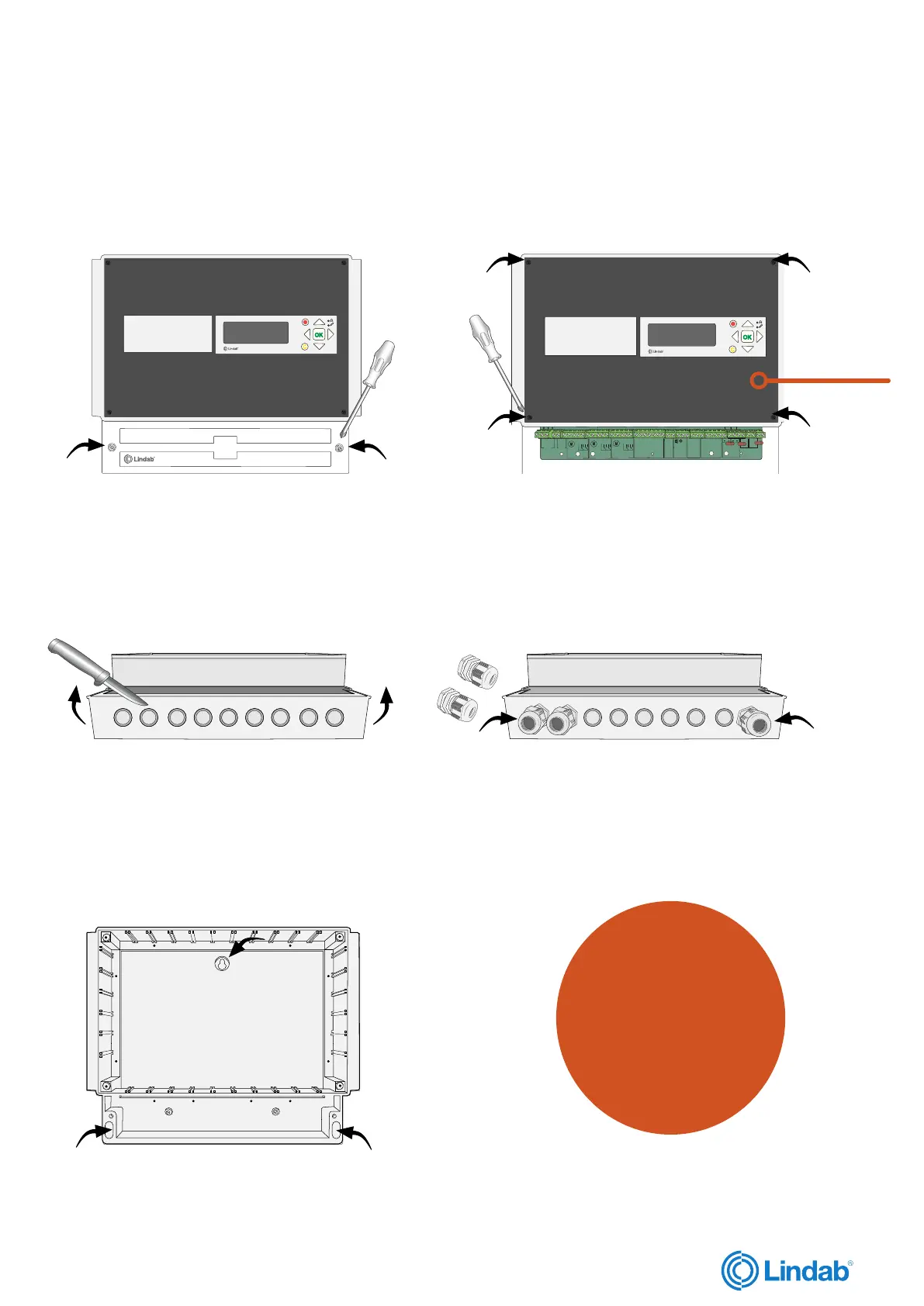
FireSystemPro Master unit
1. Unscrew the cover lid to access the circuit card.
2. Unscrew and remove the front plate to access power
supply, network cable and the rest of the circuit card.
3. Carve the holes on the bottom of the unit, to
open up for wiring cables.
Access circuit card
4. Install displacement joints before connecting cables.
5. Mount the unit on the wall
Click here to
go directly to
the datasheet
for PRO-M
Network cable