Confidential
Line 6 Confidential Page 4 of 10 7/5/2007
6. METAL CAN OSCILLATOR: Y2 (P/N 11-01-2458) and Y3 (P/N 11-01-2257) Metal
can oscillator are to be mounted flush on the Bottom Side of the PCB. Make sure to
check pin 1 orientation before installing. Add Insulator (P/N 30-15-0007) between the
PCB and Y1 (P/N 11-00-0003) before mounting onto the Top Side of the PCB.
7. ELECTROLYTIC CAPACITORS: All large capacitors are mounted flush against the
PCB on the Bottom Side of the PCB.
C141, C142, C157, C158, C159, C178, C191.
Add RTV around C170 so the capacitor can not short out to any components.
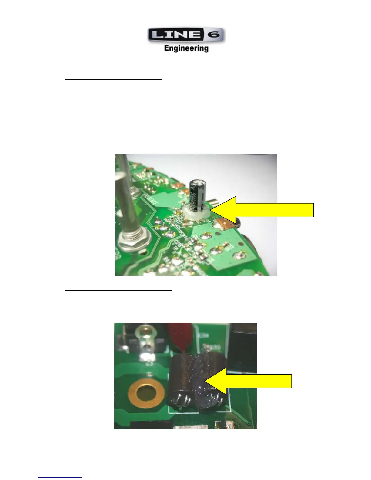
8. THRU HOLE FERRITE BEADS: L15 and L24 (P/N 04-04-0001) must be mounted on
its side flush against the PCB and lined up with silkscreen outline. Clip leads to .060” on
the TOP side of PCB. Make sure to apply a dab of RTV between L15 and L24, see
picture below.
ADD A DAB OF RTV
SURROUND C170 WITH RTV
 Loading...