EasyManuals Logo

Line 6 POD X3 User Manual

Line 6 POD X3
162 pages
To Next Page IconTo Next Page
To Previous Page IconTo Previous Page
Page #20 background imageLoading...
Page #20 background image
Confidential
Line 6 Confidential Page 3 of 10 7/5/2007
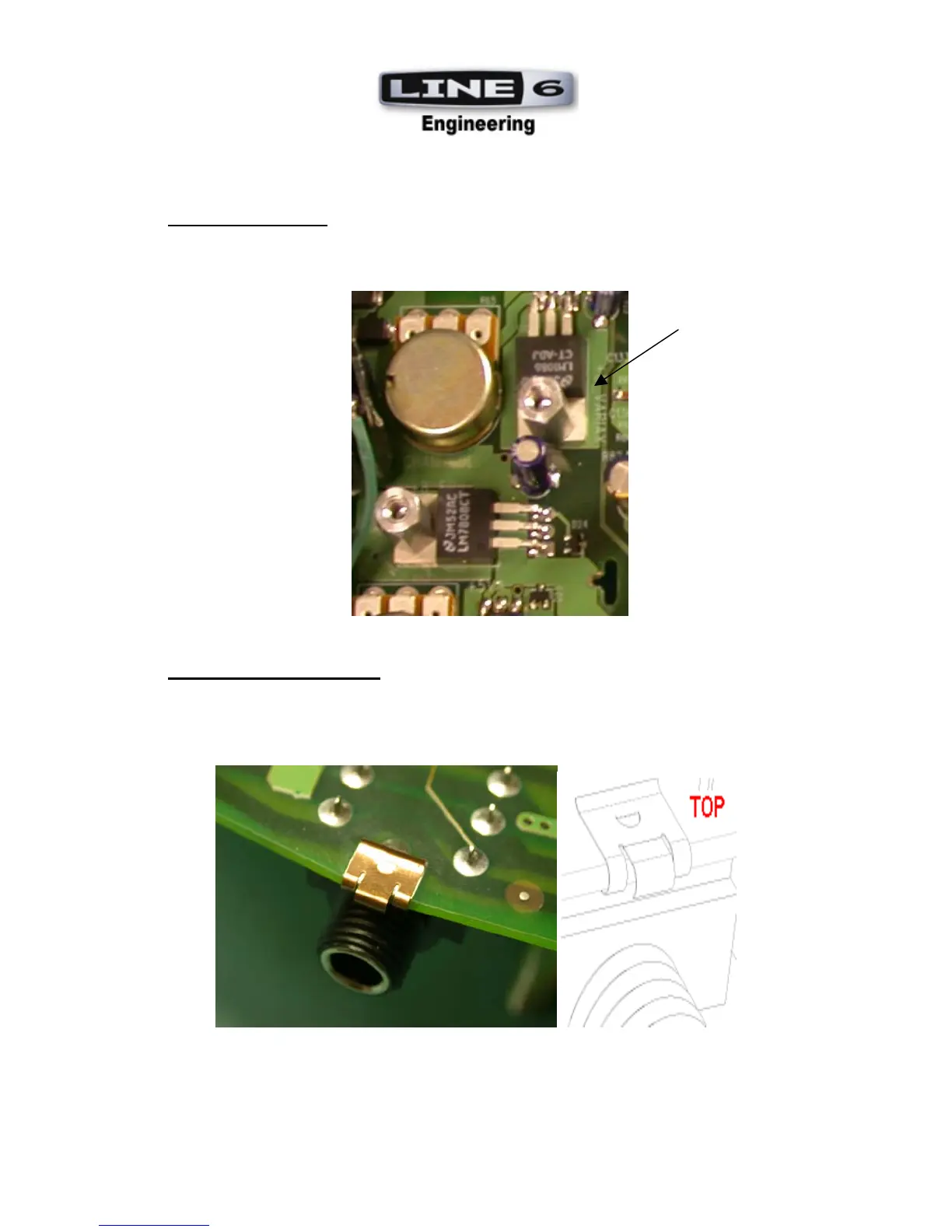
4. REGULATOR ICs: U17 is mounted with a screw (30-00-0607) and standoff (30-12-
2210) flush against the PCB, tab side down. The tab’s hole must line up with the
corresponding hole in the PCB.
5. GROUNDING FINGERS: ALL grounding fingers (GF3-5, G7-9) 30-18-3030 are
mounted flush against the PCB edge. They are mounted with their center clip hole on the
TOP side of the PCB (all jacks are on the bottom side) see drawing below. The “curl” of
the grounding finger should curve toward the bottom side (toward the corresponding jack
if there is one). They should then be manually soldered on the TOP side.

Other manuals for Line 6 POD X3

Questions and Answers:

Question and Answer IconNeed help?

Do you have a question about the Line 6 POD X3 and is the answer not in the manual?

Line 6 POD X3 Specifications

General IconGeneral
TypeMulti-Effects Processor
Amp Models78
Effects Models98
DisplayLCD
TechnologyDigital
Inputs1 x 1/4" Guitar, 1 x XLR Mic, 1 x 1/4" Aux
Outputs1 x XLR
MIDIIn/Out
USBYes
Power Supply9V AC adapter (included)

Related product manuals