LT360 Precision Turntable
User Manual
LT360 Precision Turntable
User Manual
16
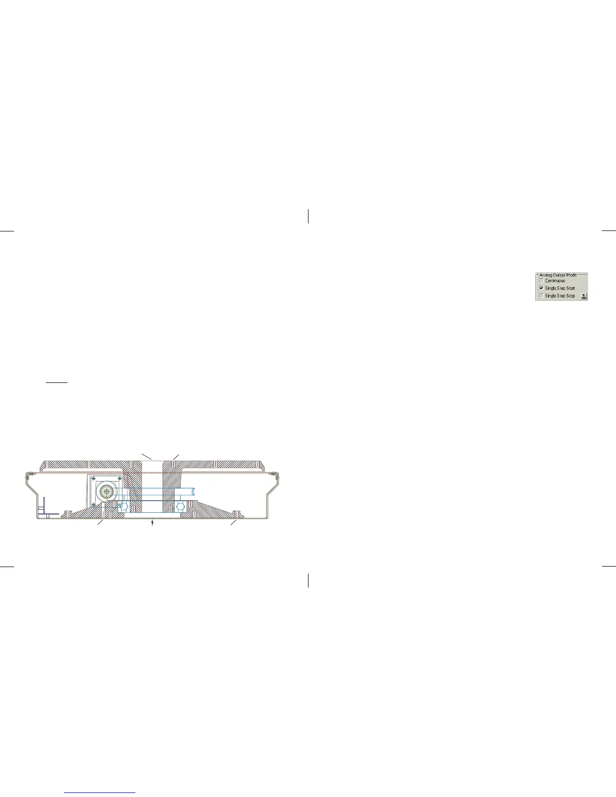
2.2 Mounting to the LT360
The LT360 drive assembly consists of two aluminum castings, platter and
base, joined through a 125mm ball bearing. The drive assembly provides
both high strength and high precision. A 1.5 In (38mm) clearance hole is
provided through the center of the assembly to route cables if needed.
The platter and base both have pre-tapped 1/4-20 machine screw holes for
mounting customer fixtures and jigs. The thread depth is 0.5 In (12mm)
minimum. When attaching screws to these tapped holes, please make sure
the screw length entering the platter or base castings does not exceed about
1/2 Inch.
Also, do not overtighten the screws which could damage the tapped holes.
Split lock washers should always be used and tightened only until the
washer is flat.
Note: Never use the chassis as structural support. Its purpose is only to
contain the internal electronics and system components.
GREASE PORT
(8) 1/4-20 TAPPED HOLES
(20) 1/4-20 TAPPED HOLESCABLE HOLE
73
■ Analog Output Mode
This selection controls the operating mode for the Analog
Output.
When Continuous is selected, the Analog Output will continuously follow
the platter position as it is moving. This is a real time output mode where
the analog output voltage always represents the current platter position.
When Single Step Start is selected, the Analog Output will only produce a
single step change output voltage representing the final destination position
at the start of the movement. For example, if the current position is 0.0
degrees and the destination is 100.0 degrees, the Analog Output voltage
will change from 0.000V to 1.000V at the start of the movement.
When Single Step Stop is selected, the Analog Output will only produce a
single step change output voltage representing the final destination position
after the movement stops. For example, if the current position is 0.0
degrees and the destination is 100.0 degrees, the Analog Output voltage
will remain at 0.000V during the movement and then change to 1.000V
when the movement stops. The final output voltage changes 2 seconds
after the platter movemet stops.
If the movement is aborted before it reaches the destination, the output
voltage will be updated to the correct final value in all modes.