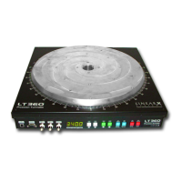
LT360 Precision Turntable
User Manual
LT360 Precision Turntable
User Manual
24
3.4 Pulse Input
The Pulse Input provides a simple and basic means of digital control. The
connector is a standard BNC and responds to 0/5V TTL or 0/3.3V LVTTL
levels. This control method is enabled/disabled by software configuration.
Each pulse will trigger a step. The step size is controlled else where. The
step can be either CW or CCW depending on the software settings.
The width of the pulse should be at least 10uSec, and the triggering can be
set on the rising or falling edge. Any pulses which occur while the LT360 is
moving will be ignored.
If you are not using the TTL pulse input, it is probably best to keep this
feature disabled to prevent false triggering due to any noise pickup at the
open connector.
65
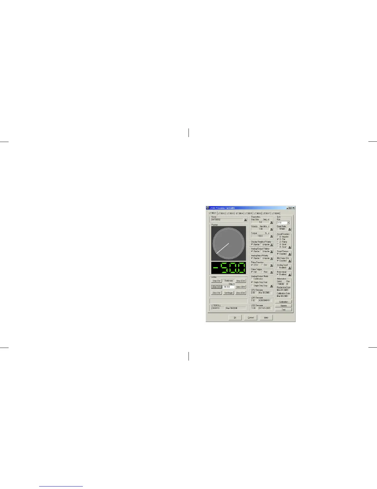
8.1 LT360 Windows Software
The application program provides full control over all of the LT360 functions
and features. Up to (8) units can be managed simultaneously, either linked
by USB or RS-232. The main window of the program is shown below.
Fields are grayed out when unlinked.
Each LT360 unit is assigned
to a tab. Changing between
tabs will load the parameters
of that unit into the controls
and parameter fields.
Two methods of displaying
current turntable position
are used: the analog platter
display, and the digital
readout.
Clicking on the platter
graphic will Abort/Stop a
move.
Clicking on the digital
readout will update the
display.