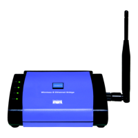
Wireless-G Ethernet Bridge
7
Instant Wireless
®
Series
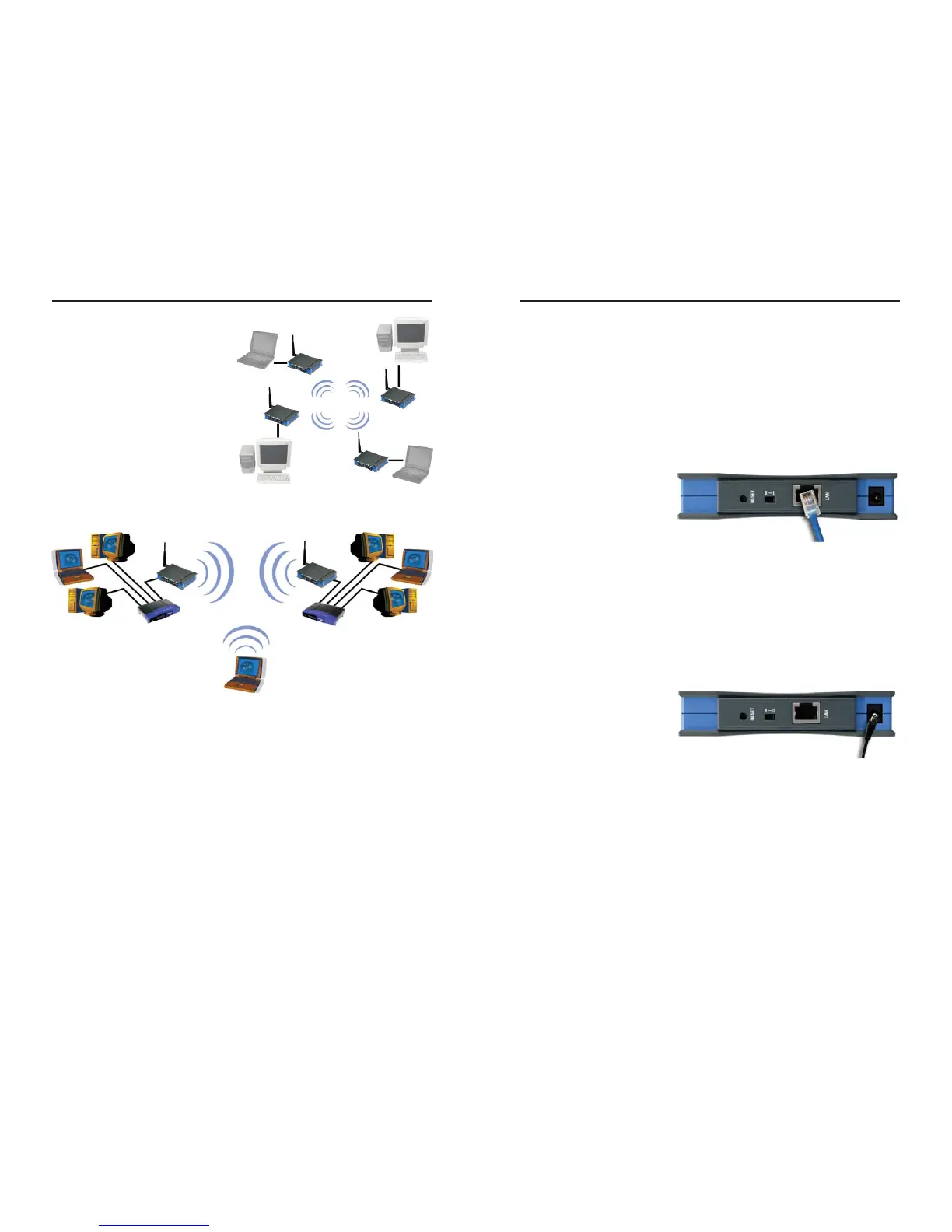
Figure 3-2 shows a typical scenario
of four Wireless-G Ethernet Bridges
in ad-hoc mode. Figure 3-3 shows a
typical wireless bridging scenario
using two Wireless-G Ethernet
Bridges. Each wireless network is
connected to a Wireless-G Ethernet
Bridge through a switch. A separate
notebook computer is equipped with
a wireless PC card and can commu-
nicate with both wireless networks as
long as it has the same SSID and
channel as both wireless networks.
6
Chapter 4: Connecting the
Wireless-G Ethernet Bridge for
Setup
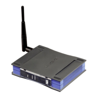
1. Attach the external antenna.
2. Plug the included Ethernet
network cable into the
LAN port on the back
panel of the Bridge.
3. The X-II (MDI/MDI-X)
slide switch offers a choice
between two settings. Slide
the X-II switch to the X position if you are connecting the Bridge to a PC’s
network adapter. Slide the X-II selection switch to the II position if you are
connecting the Bridge to a hub or switch.
4. Plug the other end of the Ethernet network cable into the RJ-45 port of the
hub, switch, or PC you wish to use to configure the Bridge.
5. Plug the supplied power
cable into the Power port
on the back panel of the
Bridge. Then plug the
other end into an electrical
outlet.
Proceed to the next section, “Chapter 5: Setting Up the Wireless-G
Ethernet Bridge.”
Figure 4-1
Figure 3-3
Figure 4-2
Figure 3-2
 Loading...