Instant Wireless
®
Series
16
Chapter 6: Connecting the
Wireless-G Ethernet Bridge for
Network Use
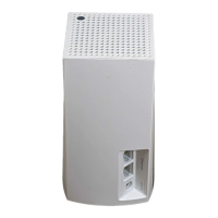
1. After configuration, unplug the power cable from the electrical outlet, and
unplug the Ethernet network cable from the PC.
2. Plug the Ethernet network cable into the RJ-45 port on the Ethernet-ready
network device you wish to add to the wireless network.
3. Plug the power cable into a local electrical outlet.
The installation of the Wireless-G Ethernet Bridge is complete. Proceed
to the next section, “Placement Options,” if you want to mount the
Bridge on a wall or have the Bridge stand on a surface.
Note: If you do not have an active connection to the Ethernet-ready
network device, then change the position of the X-II switch.
Note: The Bridge features Power Over Ethernet (PoE) support. PoE
technology allows a PoE adapter (also known as a power injector,
power hub, or inline power device) to supply data and power to an
Ethernet device using a single Ethernet network cable. To use the
Bridge’s PoE feature, follow the instructions for your specific PoE
device.
Wireless-G Ethernet Bridge
17
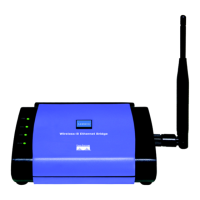
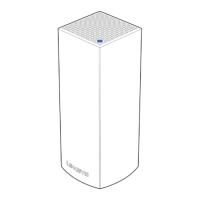
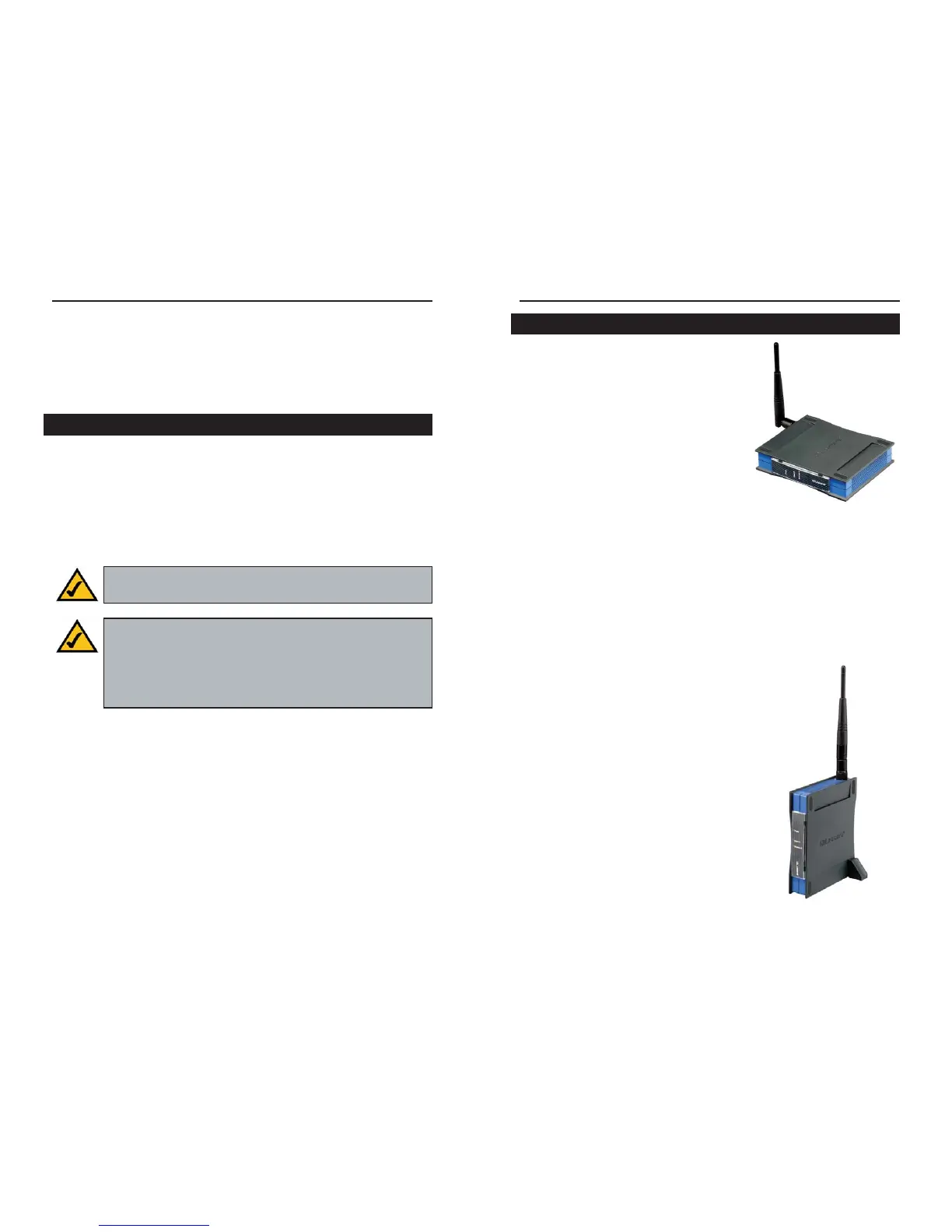
There are three ways to place the Bridge. The
first way is to place the Bridge horizontally on
a surface (see Figure 6-1). The second way is
to hang the Bridge on a wall, with the Bridge
in a vertical position. The third way is to stand
the Bridge vertically on a surface (see Figure
6-2). The second and third options are
explained in further detail below.
Wall Mount Option
1. The Bridge has eight rubber inserts, four
on each side. Depending on how you want
to mount the Bridge, remove two of the rubber inserts.
2. Attach two screws to the wall in the location where you want to mount the
Bridge.
3. Hang the Bridge off of the two screws.
Stand Option
1. The Bridge has eight rubber inserts, four
on each side. Remove the two rubber
inserts that are adjacent to the power port.
2. The Bridge includes two triangular stands.
Insert a stand into an opening. Push the
stand up to snap it into place.
3. Do the same with the second stand.
4. Place the Bridge.
The installation of the Wireless-G
Ethernet Bridge is complete.
Placement Options
Figure 6-1
Figure 6-2
Connection to a Network Device
 Loading...