Chapter 1
Product Overview
4
Wireless-G Broadband Router with 2 Phone Ports
Chapter 1:
Product Overview
Thank you for choosing the Linksys Wireless-G Broadband
Router with 2 Phone Ports. The Router lets you access
the Internet via a wireless connection or through one of
its four switched ports. You can also use the Router to
share resources such as computers, printers and files. The
built-in phone adapter enables Voice-over-IP (VoIP) calls
even while you are using the Internet.
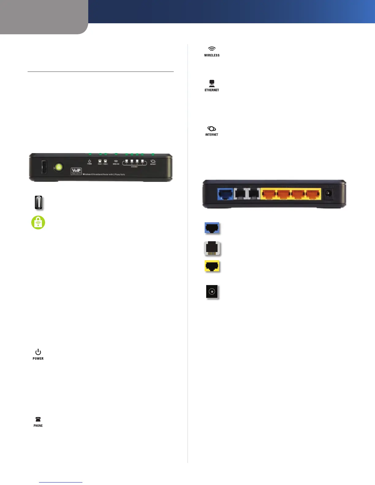
Front Panel
USB The USB port is reserved for future use.
Wi-Fi Protected Setup (White/Orange) If you
have client devices, such as wireless adapters,
that support Wi-Fi Protected Setup, then you
can use Wi-Fi Protected Setup to automatically
configure wireless security for your wireless
network(s).
To use Wi-Fi Protected Setup, run the Setup
Wizard, or refer to the “Wireless > Basic Wireless
Settings” section of “Chapter 3: Advanced
Configuration”.
The Wi-Fi Protected Setup button lights up
white and stays on while wireless security is
enabled on your wireless network(s). The LED
lights up orange if there is an error during the
Wi-Fi Protected Setup process. Make sure the
client device supports Wi-Fi Protected Setup.
Wait until the LED is off, and then try again.
Power (Green/Red) The Power LED lights up
green and stays on while the Router is powered
on. When the Router goes through its self-
diagnostic mode during every boot-up, the LED
will flash. When the diagnostic is complete, it
will be solidly lit green. If the LED lights up red,
make sure the correct power adapter is used.
If the LED remains red, contact your service
provider for support.
Phone 1-2 (Green) The Phone 1 or 2 LED lights
up and stays on when an active line is registered
to the corresponding port on the Router’s back
panel. The LED slowly flashes when voicemail
messages are waiting.
Wireless (Green) The Wireless LED lights up
when the wireless feature is enabled. It flashes
when the Router is actively sending or receiving
data over the network.
Ethernet 1-4 (Green) These numbered LEDs,
corresponding with the numbered ports on the
Router’s back panel, serve two purposes. If the
LED is solidly lit, the Router is connected to a
device through that port. It flashes to indicate
network activity over that port.
Internet (Green) The Internet LED lights up
and stays on when there is a connection made
through the Internet port. It flashes to indicate
network activity over the Internet port.
Back Panel
Internet The Internet port is where you will
connect your cable or DSL Internet connection.
Phone 1-2 The Phone ports connect standard
analog telephones to the Router.
Ethernet 1, 2, 3, 4 These Ethernet ports (1, 2, 3,
4) connect the Router to wired computers and
other Ethernet network devices.
Power The Power port is where you will
connect the power adapter.
 Loading...