Separate Ins••lated Loops
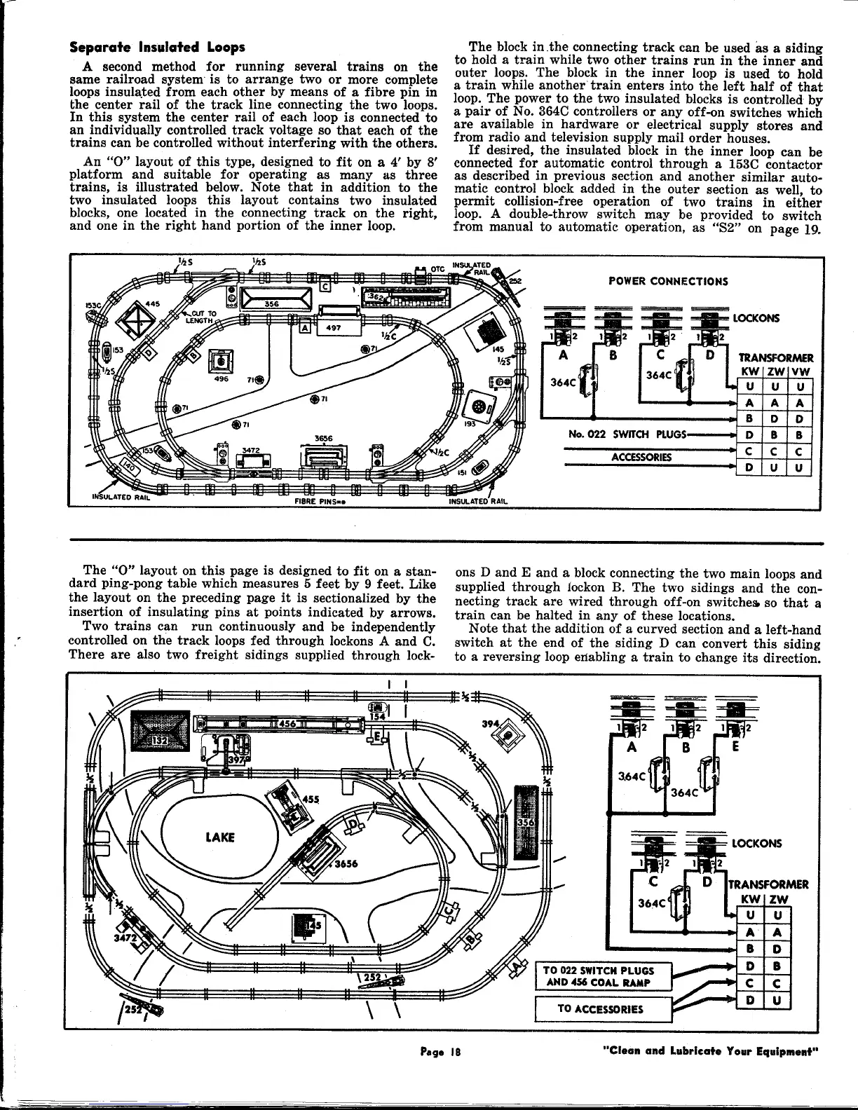
A second method for running several trains on the
same railroad system is to arrange two or more complete
loops insula.ted from each other by means of a fibre pin in
the center rail of the track line connecting the two loops.
In this system the center rail of each loop is connected to
an individually controlled track voltage so that each of the
trains can be controlled without interfering with the others.
An
"0"
layout of this type, designed to fit on a 4' by 8'
platform and suitable for operating as many as three
trains, is illustrated below. Note that in addition to the
two insulated loops this layout contains two insulated
blocks, one located in the connecting track on the right,
and one in the right hand portion of the inner loop.
The block in .the connecting track can be used as a siding
to hold a train while two other trains run in the inner and
outer loops. The block in the inner loop is used to hold
a train while another train enters into the left half of that
loop. The power to the two insulated blocks is controlled by
a pair of No. 364C controllers or any off-on switches which
are available in hardware or electrical supply stores and
from radio and television supply mail order houses.
If desired, the insulated block in the inner loop can be
connected for automatic control through a
153C
contactor
as described in previous section and another similar auto-
matic control block added in the outer section as well, to
permit collision-free operation of two trains in either
loop. A double-throw switch may be provided to switch
from manual to automatic operation, as "82" on page
19.
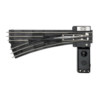
No. 022 SWITCH PLUGS
ACCESSORIES
TRANSFORMER
KW ZW VW
U U U
A A A
B D D
D B B
C C C
D U U
The
"0"
layout on this page is designed to fit on a stan-
dard ping-pong table which measures 5 feet by 9 feet. Like
the layout on the preceding page it is sectionalized by the
insertion of insulating pins at points indicated by arrows.
Two trains can run continuously and be independently
controlled on the track loops fed through lockons A and C.
There are also two freight sidings supplied through lock-
ons D and E and a block connecting the two main loops and
supplied through 10ckon B. The two sidings and the con-
necting track are wired through off-on switches. so that a
train can be halted in any of these locations.
Note that the addition of a curved section and a left-hand
switch at the end of the siding D can convert this siding
to a reversing loop enabling a train to change its direction.
TRANSFORMER
KW ZW
U U
A A
B D
D B
C C
D U
TO 022 SWITCH PLUGS
AND 456 COAL RAMP
 Loading...