1015 - 1016
1053 - 1063
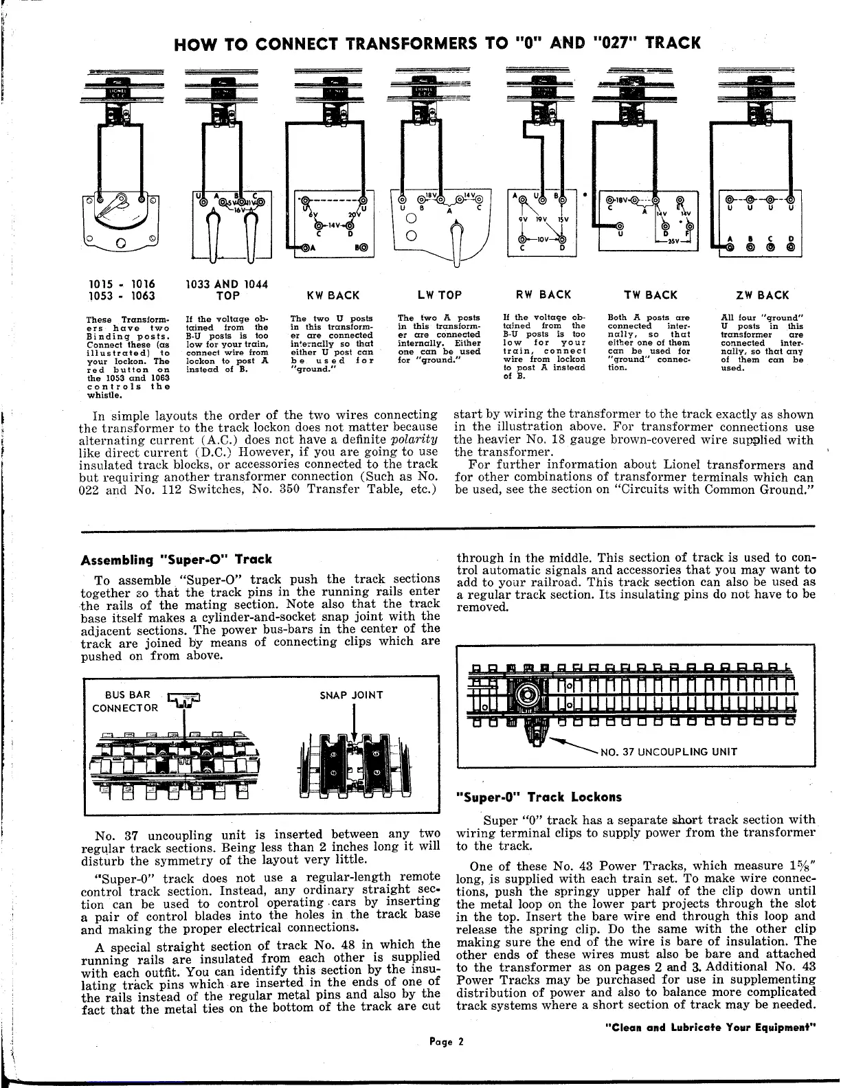
These Transform-
ers have two
Binding posts.
Connect these (as
illustrated) to
your lockon. The
red button on
the 1053 and 1063
controls the
whistle.
1033 AND 1044
TOP
If the voltage ob-
tained from the
B-U posts is too
low for your train,
connect wire from
lockon to post A
instead of B.
.~-------~
~14V-:
C D
" I@
@>oIlY 0 ---
a ~
C A. 14Y I:~v
~Mvl
The two U posts
in this transform-
er are connected
inte;nc:lly so that
either U post can
be used for
"qround."
The two A posts
in this· transform-
er are connected
internally. Either
one can be used
for "ground."
All
four
"ground"
U posts in .this
transformer are
connected inter-
nally, so that any
of them can be
used.
In simple layouts the order of the two wires connecting
the transformer to the track lockon does not matter because
alternating current (A.C.) does net have a definite
polarity
like direct current (D.C.) However, if you are going to use
insulated track blocks, or accessories connected to the track
but requiring another transformer connection (Such as No.
022
and No.
112
Switches, No.
350
Transfer Table, etc.)
II the voltage ob-
tained from the
B-U posts is too
low for your
train, connect
wire from lockon
to post A instead
of
B.
Both A posts are
connected inter-
nally, so that
eHher one of them
can be used for
"ground" connec~
tion.
start by wiring the transformer to the track exactly as shown
in the illustration above. For transformer connections use
the heavier No. 18 gauge brown-covered wire sup~lied with
the transformer.
For further information about Lionel transformers and
for other combinations of transformer terminals which can
be used, see the section on "Circuits with Common Ground."
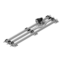
Assembling "Super.O" Track
To assemble. "Super-O" track push the track sections
together so that the track pins in the running rails enter
the rails of the mating section. Note also that the track
base itself makes a cylinder-and-socket snap joint with the
adjacent sections. The power bus-bars in the center of the
track are joined l:>ymeans of connecting clips which are
pushed on from above.
BUS BAR
CONNECTOR
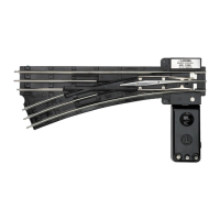
No. 37 uncoupling unit is inserted between any two
regl1lar track sections. Being less than 2 inches long it will
disturb the symmetry of the layout very little.
"Super-O" track does not use a regular-length remote
control track section. Instead, any ordinary straight sec·
tion can be used to control operating. cars by inserting
a pair of control blades into the holes in the track base
and making the proper electrical connections.
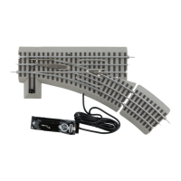
A special straight section of track No. 48 in. which ~he
running rails are insulated from each other
IS
supplIed
with each outfit. You can identify this section by the insu-
lating track pins which are inserted in .the ends of one of
the rails instead of the regular metal pms and also by the
fact that the metal ties on the bottom of the track are cut
through in the middle. This section of track is used to con-
trol automatic signals and accessories that you may want to
add to your railroad. This track section can also be used as
a regular track section. Its insulating pins do not have to be
removed.
"Super-O" Track Lockons
Super "0" track has a separate &hart track section with
wiring terminal clips to supply power from the transformer
to the track. .
One of these No. 43 Power Tracks, which measure
1%"
long, is supplied with each train set. To make wire connec-
tions, push the springy upper half of the clip down until
the metal loop on the lower part projects through the slot
in the top. Insert the bare wire end through this loop and
release the spring clip. Do the same with the other clip
making sure the end of the wire is bare of insulation. The
other ends of these wires must also be bare and attached
to the transformer as on pages 2 and 3. Additional No. 43
Power Tracks may be purchased for use in supplementing
distribution of power and also to balance more complicated
track systems where a short section of track may be needed.
i
"Clean and Lubricate Your Equipment"
~ •••t
p_a_9_e_2 _
 Loading...