4'1~JI
7S~ 32
1I~ "
2
e:r "
3
lIIliiiIl!l!!!I ,•
• Hb 37
10
IE3! "
7
[» ,••
1
!1!!!1!!!lill!"
I~ ••
7
VI
62
~:::::~"2
®
T~~~~Le
, • ~~~U1Le:T~~ll
[g
fBl
v
'tf
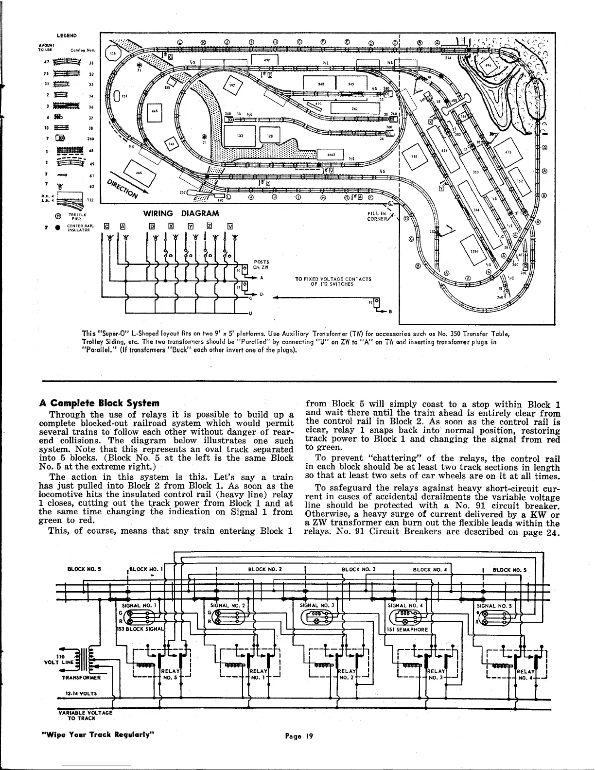
WIRING DIAGRAM
IQJ
rgJ
1YJ [l] 1YI
!
f'tff
l~
o
0
~o
0
This "Super-O" L-Shaped layout fits on two 9' xS' platforms. Use Auxiliary Transformer (TW) for accessories such as No. 350 Transfer Table,
Trolley Siding, etc. The two transforMers should be "Parol led" by connecting "U" on ZW to "A" on TW C2I1dinserting transformer plugs in
"Parallel,"
(Ii
transformers "Buck" each other invert one of the plugs);
A Complete Block System
Through the use of relays it is possible to build upa
complete blocked-out railroad system which would permit
several trains to follow each other without danger of rear-
end collisions. The diagram below illustrates one such
system. Note that this represents an oval track separated
into 5 blocks. (Block No.5 at the left is the same Block
No.5 at the extreme right.)
The action in this system is this. Let's say a train
has just pulled into Block 2 from Block 1. As soon as the
locomotive hits the insulated control rail (heavy line) relay
1 closes, cutting out the track power from Block 1 and at
the same time changing the indication on Signal 1 from
green to red.
This, of course, means that any train entering Block 1
from Block 5 will simply coast to a stop within Block 1
and wait there until the train ahead is entirely clear from
the control rail in Block 2. As soon as the control rail is
clear, relay 1 snaps back into normal position, restoring
track power to Block 1 .and changing the signal from red
to green.
To prevent "chattering" of the relays, the control rail
in each block should be at least two track sections in length
so that at least two sets of car wheels are on it at all times.
To safeguard the relays against heavy short-circuit cur-
rent in cases of accidental derailments the variable voltage
line should be protected with a No. 91 circuit breaker.
Otherwise, a heavy surge of current delivered by a KW or
a ZW transformer can burn out the flexible leads within the
relays. No. 91 Circuit Breakers are described on page 24.





 To Next Page