Rev: 09.02.21 Page 4 CCD-0004395
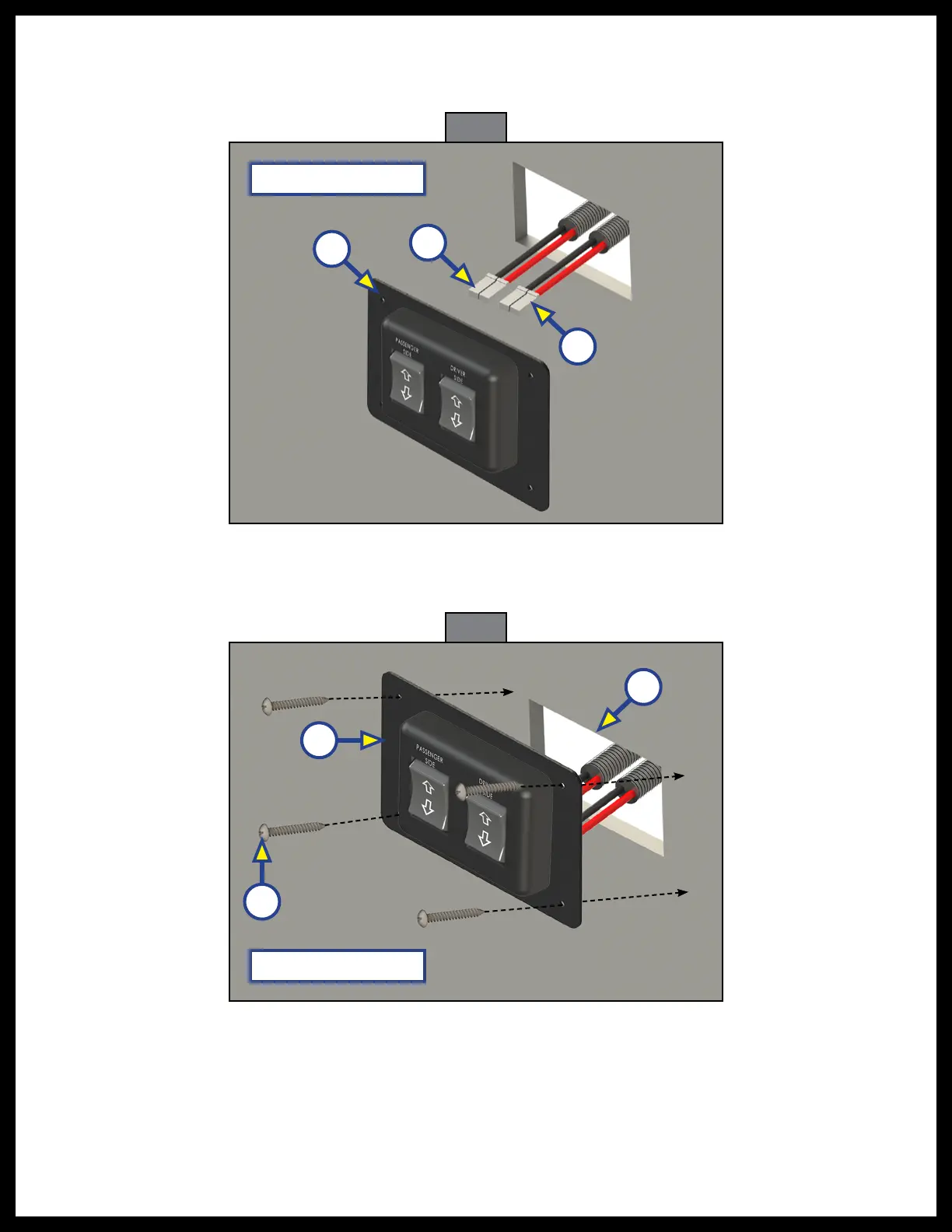
3. Feed the two landing gear harnesses ends (Fig. 2A) through compartment hole and attach to the
appropriate switch panel (Fig. 2B) harness receptors, see Wiring the Switch Panel and Landing Gear
and Wiring Diagram sections for complete wiring instructions.
4. Place the switch panel plate (Fig. 3A) centered over the the compartment hole (Fig. 3B). Attach the
switch panel plate with four #8 x 1" screws (Fig. 3C) or screws with sufficient length to thread into the
compartment wall.
Compartment Wall
Fig. 3
Compartment Wall
Fig. 2
A
A
B
A
B
C