Rev: 09.02.21 Page 3 CCD-0004395
The “CAUTION” symbol above is a sign that a safety risk is involved and may cause personal injury
and/or product or property damage if not safely adhered to and within the parameters set forth
in this manual. Always wear eye protection when performing service, maintenance or installation
procedures. Other safety equipment to consider would be hearing protection, gloves and possibly
a full face shield, depending on the nature of the task.
Resources Required
Moving parts can pinch, crush or cut. Keep clear and use caution.
Installation of Prep Kit
Switch Panel Installation
1. Determine where to mount the switch panel. The switch panel should be mounted in a compartment
on the passenger or driver's side of the 5th wheel so the operator will have a view of the coupler while
using the switch panel.
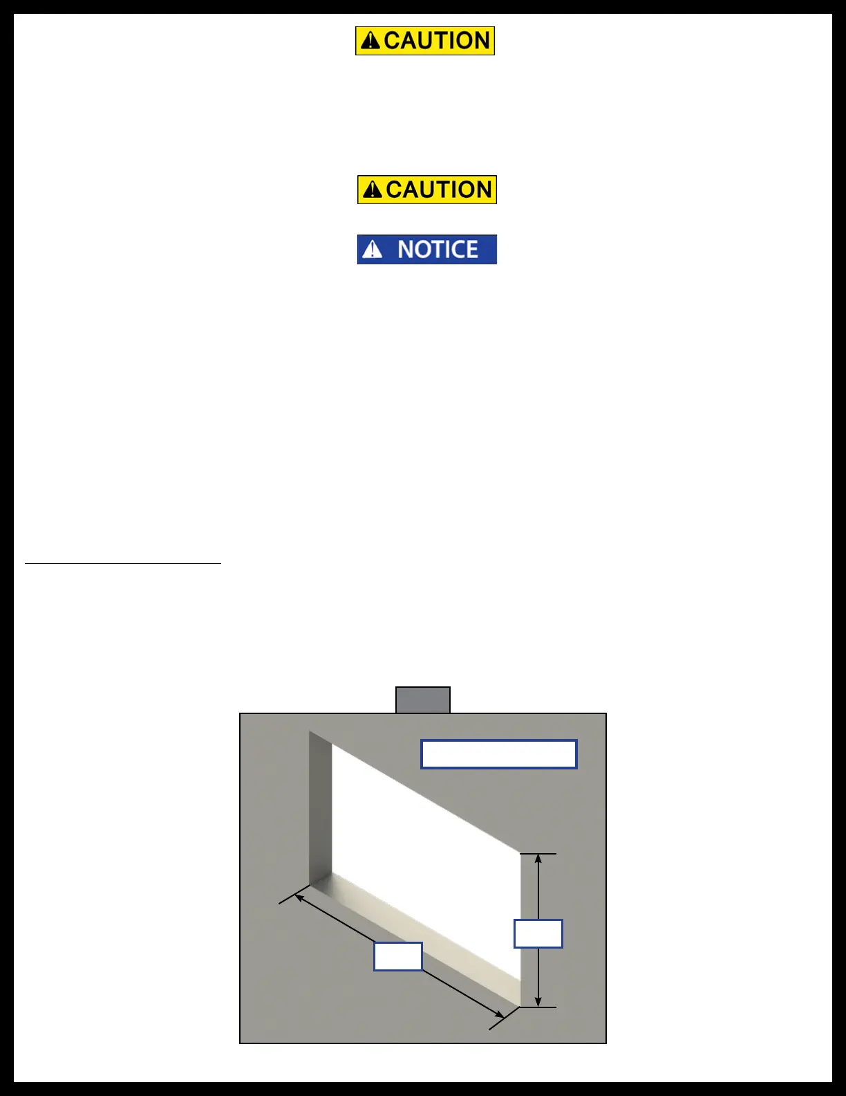
2. Cut a hole in the wall of the compartment 3 3/8” wide by 2 3/4” high (Fig. 1) so the top and bottom
horizontal cuts are parallel to the floor of the compartment.
All electrical wiring harnesses shall be loomed and secured to prevent possible damage and
installed in accordance with RVIA electrical standards.
Compartment Wall
2 ¾"
3 ⁄"
Fig. 1
• Cordless or electric drill
or screw gun
• Appropriate drive bits
• #8 X 1" wood screws or self-tapping screws
depending on backer material
• Air saw with cutting blades
• Electrical connectors
• Seal foam
• 30 amp auto-reset circuit breaker
• 50 amp breaker
• 6 AWG wire
• Tape measure
• Marker