Rev: 09.02.21 Page 5 CCD-0004395
Wiring the Switch Panel and Landing Gear
NOTE: Circuit protection is not supplied. LCI recommends a 30 amp auto-reset circuit breaker for this
system and prep a 50 amp circuit breaker, placed in line with the power source for the future
upgrade installation. See the Wiring Diagram section to complete these steps. OEM will need to
supply miscellaneous wiring and wiring connectors. A minimum of 6 AWG wire is needed on all
power and ground wiring.
1. Connect the positive wire from the switch (Fig. 4C) to the 30 amp auto-reset circuit breaker.
See the Wiring Diagram section.
2. Connect the wire from the 30 amp auto-reset circuit breaker to the power source.
3. Mount and prep a 50 amp circuit breaker to be in line with the power source. This 50 amp circuit
breaker will be used for the future upgrade installation. Prep wire from the 50 amp circuit breaker with
a bell cap end. See the Wiring Diagram section.
4. Connect the negative wires from the switch (Fig. 4A) to the negative terminal of the battery.
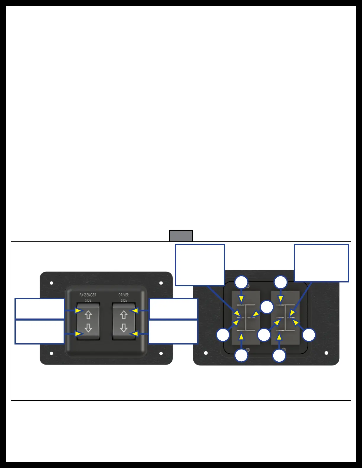
5. Plug both passenger's side and driver's side harnesses into their respective connectors on the
switch (Fig. 4B).
A. Connect the driver side landing gear harness red wire to the terminal (Fig. 4B).
B. Connect the driver side landing gear harness black wire to the terminal (Fig. 4C).
C. Connect the passenger side landing gear harness red wire to the terminal (Fig. 4D).
D. Connect the passenger side landing gear harness black wire to the teriminal (Fig. 4 E).
6. Connect the positive wires from the switch (Fig. 4F) to the 30 amp circuit breaker.
7. Plug both passenger's side and driver's side harnesses into their respective landing gear jacks, see the
Wiring Diagram section.
NOTE: Only the two-wire connector off of the landing gear motor will be used for the switch panel harness.
The other wire connection from the motor is for a future optional leveling system.
Fig. 4
Driver's Side
Landing Gear
Harness
Connection
Passenger Side
Landing Gear
Harness
Connection
A
B
F
F
E
Landing Gear
Up
Landing Gear
Down
Landing Gear
Up
Landing Gear
Down
A
D
C