Rev: 09.02.21 Page 6 CCD-0004395
Middle and Rear Jack Harnesses
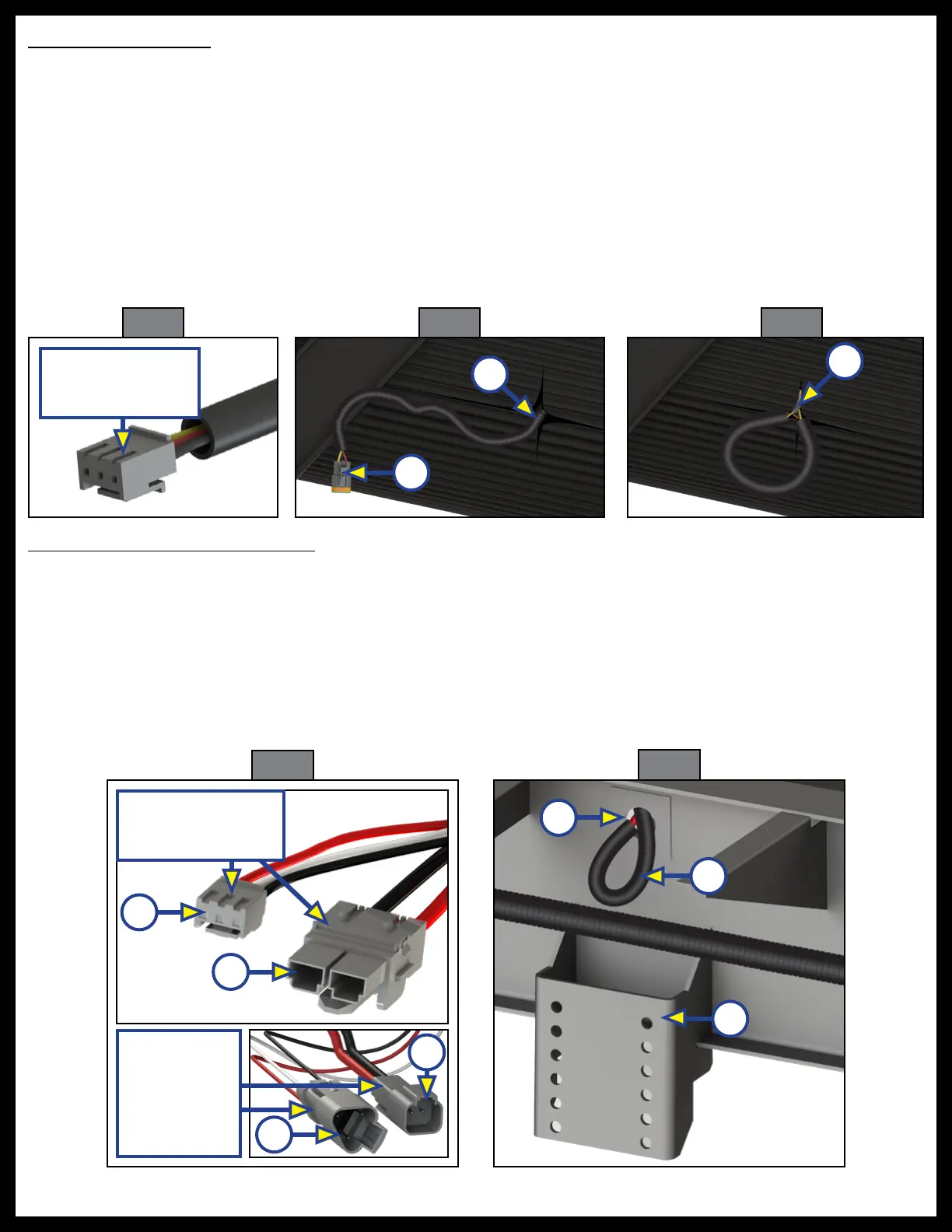
1. Lay the controller end connections (Fig. 8A) of the four jack harnesses in the bottom of the same
compartment as the rear sensor harness.
2. Run the jack connection ends (Fig. 8B) of the jack harness to the future jack locations through the same
compartment hole as the rear sensor harness. Run the harnesses to their respective jack locations, and
out through the chassis penetrations (Fig. 9A) above the jack brackets (Fig. 9B).
3. Make sure there is plenty of jack harness (Fig. 9B) length out from the chassis hole to attach to the
future jack motor and loop the jack harness end back into the chassis penetration (Fig. 9A).
4. Use seal foam to fill and secure the jack harness wire in the chassis penetration location (Fig. 9A).
Rear Sensor Harness
1. In the same compartment as the switch panel, create a separate hole that will allow access to the
inside chassis area or use any gap in the compartment walls.
NOTE: Allow ample harness excess at both ends to ensure room for future installation connection to the
controller and sensor.
2. Lay the controller end of the rear sensor harness (Fig. 5) in the bottom of the compartment and
run the opposite end of the harness through the inside bottom of the underbelly to the rear center
of the underbelly.
3. Cut a small slit in the underbelly (Fig. 6A) to allow access to bring the rear sensor harness end (Fig. 6B) through
the slit in the underbelly.
4. Loop the rear sensor harness end (Fig. 6B) back into the underbelly slit (Fig. 7A).
A
C
Fig. 9
Fig. 8
Jack Harness
Ends to
Future
Leveling
Jacks
A
A
B
Fig. 7
Fig. 6
A
B
Fig. 5
Controller End of
Sensor Harness
A
Controller Ends of
Jack Harness
B
B