Rev: 07.30.18 Page 2 CCD-0001522
Safety and System Information
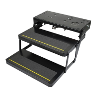
The Ground Control® 3.0 Landing Gear operates independently on uneven terrain. The landing gear features
minimal wiring with each landing gear having an in-line fused link to allow the landing gear to amp-out
when coming into contact with the ground. The 20 amp auto-reset circuit breakers on each landing gear
also work as amp limiters. When an out-of-sync landing gear is fully retracted, the breaker will trip and allow
the other landing gear to fully retract to synchronize both landing gear again.
NOTE: Qualified personnel are required to install the Ground Control 3.0 Landing Gear system.
NOTE: The landing gear system is for 5th wheel applications only.
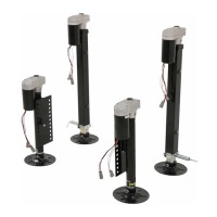
TABLE OF CONTENTS
Safety and System Information 2
Installation 3
Landing Gear 3
Wiring Landing Gear 4
Wiring Diagram 5
Operation 6
Prior to Operation 6
Extending Landing Gear 6
Retracting Landing Gear 6
Notes 7
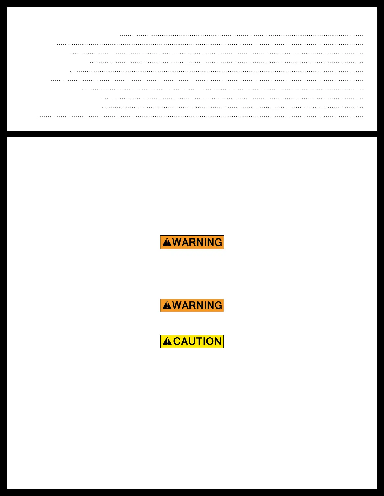
Moving parts can pinch, crush or cut. Keep clear and use caution.
The trailer MUST be supported per manufacturer's specications before working underneath. Failure to
do so may result in death or serious injury.
The “WARNING” symbol above is a sign that an installation procedure has a safety risk involved and may
cause death or serious injury if not performed safely and within the parameters set forth in this manual.
Always wear eye protection when performing this installation procedure. Other safety equipment to
consider would be hearing protection, gloves, and possibly a full face shield, depending on the nature of
the installation procedure.
 Loading...