Rev: 05.12.21 Page 2 CCD-0001770
Safety Information
Resources Required
• Cordless or electric drill or screw gun
• Appropriate drive bits
Motor Removal
NOTE: LCI recommends that the assembly be done on a clear
workbench to prevent damage to the system.
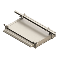
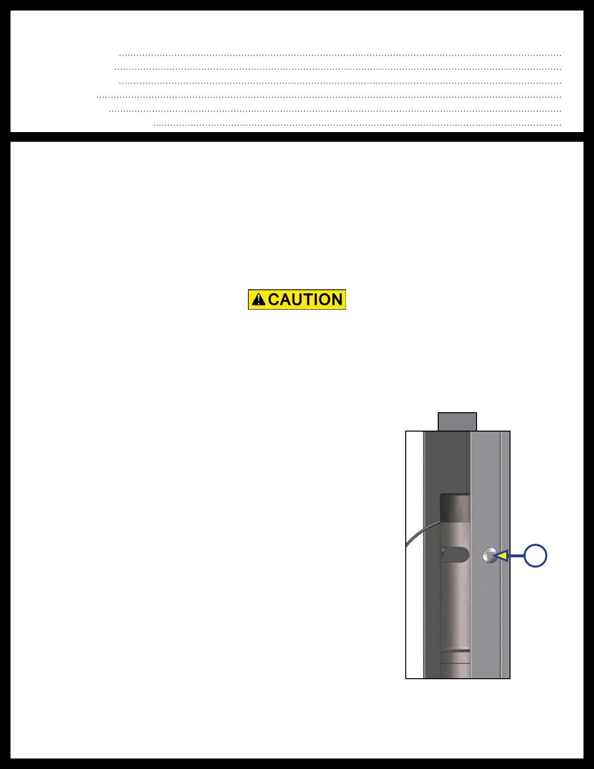
1. In order to install the gear racks, the motor needs to be
removed. The motor is held in place by a retention screw
(Fig. 1A). It is typically located on the exterior side of the
column, near the motor ventilation holes (Fig. 1). Removal
of the retention screw will allow the motor to easily slide
out of the column.
2. Set the motor and screw aside for later re-assembly.
TABLE OF CONTENTS
System Information 2
Safety Information 2
Resources Required 2
Motor Removal 2
Timing Procedure 3
Installing Shipping Angles 5
Fig. 1
A
Moving parts can pinch, crush or cut. Keep clear and use caution during assembly.
System Information
The Lippert Components, Inc. In-Wall® Slide-Out System can now be shipped disassembled at the large
components level. This means that some assembly will be required prior to the installation of the
In-Wall® Slide-Out System onto the slide-out room. The following instructions are supplied as a guide
to the proper assembly of the shipped components for the best possible functioning and operation of
the In-Wall® Slide-Out System. This manual is to be used in conjunction with the In-Wall® Slide-Out
OEM Installation Manual.

 Loading...