Rev: 05.12.21 Page 4 CCD-0001770
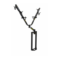
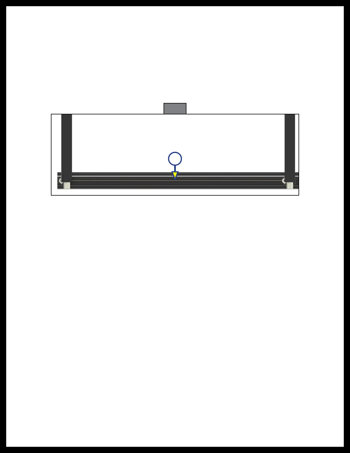
Fig. 5
A
4. Hand turn the torque shaft (Fig. 5A) until both gear racks move up and both gear racks are located at
the initial stage on the spur gear.
5. Apply downward pressure to one of the gear racks. This will cause both gear racks to move
simultaneously on their respective spur gear. At this point, the gear racks will be synchronized.
6. Move the gear racks on the H-column to an approximate center location. Make sure the H-column is
not covering any screw holes of the gear rack.
7. Re-install the motor and retention screw into the H-column.
8. Once both gear racks are engaged, use a tape measure and measure from the column to the end
of each gear rack. The measurements must be the same to ensure that the slide room will be timed
correctly.
9. Repeat steps 1-8 for the other In-Wall Slide-Out assembly.
 Loading...