Solera
®
Awning
Smart Arm
Installation and Owner’s Manual
(For Aftermarket Applications)
www.lci1.com 574-537-8900
Page 6
Solera® Awning Smart Arm Aftermarket Manual
Installation of Smart Arm™
Touch Pad
1. At the top of the drive side mount arm, locate the red power
wire and the red extend “EXT IN” wire and twist together�
Locate the black power wire and the black retract “RET IN”
wire and twist together�
2. Touch the loose end of the red wires in step #1 to the
positive post on the battery� Touch the loose end of the black
wires in step #1 to the negative post on the battery�
3. Fully extend the awning�
4. Wires can be separated at this time�
5. Finish the task of securing the mount arms� Make sure the
awning assembly is square on the unit prior to completion�
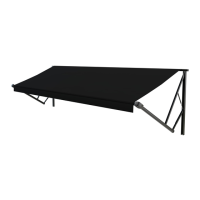
Use two #14 x 1 ¼” screws in one of the provided locations
in the middle of the arm (Fig.7), and two #14 x 1 ¼” screws
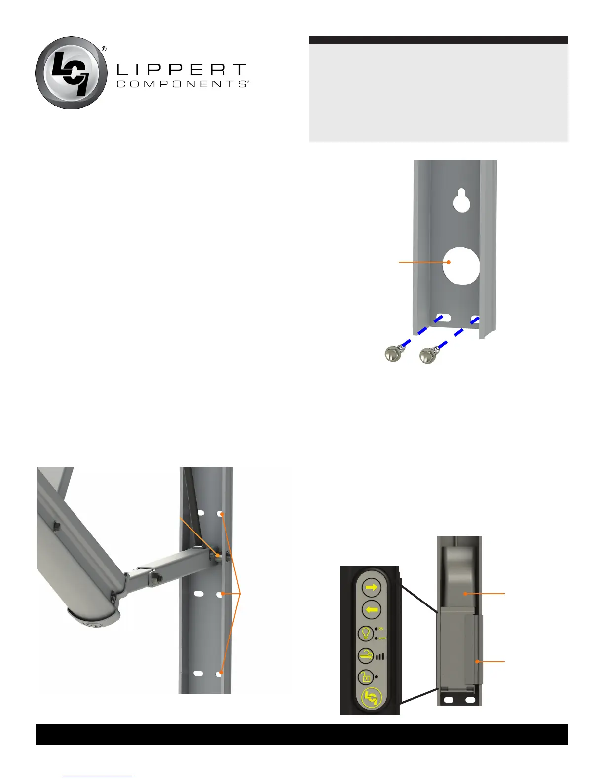
(Fig. 8) in the bottom of the arm�
NOTE: Four rivets with ⁄” grip range can be used in place of
the two middle and two lower screws on laminated walls�
NOTE: Step #5 and step #6 refer to a bottom wire connection�
If it is a top wire connection proceed to step 8�
6. At this point, determine whether this is a top or bottom wire
installation� If it is a bottom wire installation, pull the power wire
and the switch wire (red/black/green) down from the top of the
arm to the bottom�
7. Remove the wire covers from the wall mount on the drive
side, including the small wire cover at the lower portion of the
wall mount�
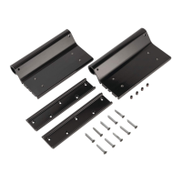
8. Remove the Smart Arm Touch Pad from the wall mount
by removing the snap clip on the right side of the touch pad
(Fig.9)� This will allow the touch pad to be removed from
the arm (Fig.9)�
possible
fastener
locations
Fig.8
snap clip
Fig.9
wire cover
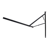
Fig.7
mount arm
access hole
side view
of arm -
touch pad
all wires must
remain on the
outside of the pin